JTAG vs SWD vs BDM vs SPI vs I2C: Which Programming Protocol Should You Use?
Modern automotive electronic systems contain a wide range of microcontrollers, memory devices and processors. These components do not all communicate through the same programming interface. Depending on the chip architecture, technicians may encounter JTAG, SWD, BDM, SPI or I2C when performing chip programming and automotive electronic repair.
Understanding the differences between these programming protocols is important for technicians who work with ECU repair, chip reading and writing, module cloning, dashboard repair, body control modules and other automotive electronic applications.
What Is a Programming Protocol?
A programming protocol defines how a programmer communicates with an electronic chip or processor.
The protocol determines how data is transferred between the programming equipment and the target device. Different chip manufacturers and processor families can use different interfaces, so a programmer designed for professional automotive electronics often needs to support multiple protocols.
Five interfaces frequently encountered in professional chip programming are:
- JTAG
- SWD
- BDM
- SPI
- I2C
These interfaces are not interchangeable. The correct protocol must be selected according to the specific chip and its supported programming method.
JTAG Programming
JTAG is a widely used interface for testing, debugging and programming electronic devices.
JTAG can provide access to certain microcontrollers and processors and is commonly associated with development, debugging and low-level programming operations.
In automotive electronics, JTAG may be encountered when technicians need direct access to a supported processor or control module.
Typical Characteristics of JTAG
- Used with selected processors and microcontrollers
- Can provide low-level device access
- Used for programming and debugging on supported devices
- Requires the correct pinout and device configuration
- Useful for advanced electronic repair applications
JTAG should not be selected simply because a chip contains a particular number of pins. The exact device and supported JTAG implementation must be confirmed before connection.
SWD Programming
SWD stands for Serial Wire Debug. It is a programming and debugging interface commonly associated with ARM-based microcontrollers.
Compared with traditional JTAG implementations, SWD can use a smaller number of signal connections while providing access to supported ARM devices.
Typical Characteristics of SWD
- Commonly used with supported ARM microcontrollers
- Designed for serial debugging and programming
- Uses a compact connection interface
- Suitable for selected automotive electronic controllers
- Requires correct device identification and pinout information
Because different manufacturers can implement devices differently, technicians should always verify the exact microcontroller before selecting SWD.
BDM Programming
BDM stands for Background Debug Mode. It is a programming and debugging interface associated with certain processor families, particularly older automotive electronics using Motorola and Freescale processor architectures.
BDM can provide direct access to supported processors and may be used during ECU repair, data backup and programming operations.
Typical Characteristics of BDM
- Associated with selected processor families
- Provides direct processor-level access
- Used for programming and debugging on supported devices
- Can be encountered in automotive ECU applications
- Requires the correct processor and connection method
When working with older ECUs, identifying the processor family is particularly important because the required programming interface may differ significantly between ECU generations.
SPI Programming
SPI stands for Serial Peripheral Interface. It is a common communication interface used between electronic components.
SPI memory devices can be found in various automotive electronic modules. Depending on the application, SPI may be used for Flash memory or other supported memory devices.
Typical Characteristics of SPI
- Common in memory devices
- Used for serial data communication
- Can be found in ECU and other automotive modules
- Useful for supported Flash and memory programming operations
- Requires correct identification of the memory device
SPI programming can be particularly useful when technicians need direct access to a supported memory chip rather than communicating with the complete ECU through a vehicle diagnostic interface.
I2C Programming
I2C stands for Inter-Integrated Circuit. It is another serial communication interface used by many electronic components.
I2C uses a shared communication bus and is commonly found in memory devices and other electronic components.
Typical Characteristics of I2C
- Uses a serial communication bus
- Commonly found in memory devices
- Can support multiple devices on the same bus
- Used in selected automotive electronic modules
- Requires correct chip identification and connection information
For automotive technicians, understanding I2C is useful when working with supported memory chips in ECUs, dashboards, body control modules and other electronic systems.
JTAG vs SWD vs BDM vs SPI vs I2C
| Protocol | Common Application | Typical Device Type | Main Consideration |
|---|---|---|---|
| JTAG | Programming and debugging | Processors and microcontrollers | Correct processor and JTAG implementation |
| SWD | Programming and debugging | Supported ARM microcontrollers | Correct ARM device and SWD pinout |
| BDM | Programming and debugging | Selected processor families | Processor architecture and supported BDM method |
| SPI | Memory programming | Flash and other supported memory devices | Correct memory type and pinout |
| I2C | Memory and device communication | EEPROM and other supported devices | Correct device address and connection |
How Do You Choose the Correct Programming Protocol?
The correct protocol should be determined by the target chip rather than by the vehicle brand alone.
A professional identification process should begin with the following information:
- Vehicle manufacturer
- Vehicle model
- ECU manufacturer
- ECU part number
- Hardware number
- Processor manufacturer
- Processor model
- Memory chip model
- Available programming interface
Once the chip or processor has been identified, technicians can determine which programming protocol is supported.
Why Chip Identification Is So Important
Two chips can have similar physical packages while using completely different communication methods.
Similarly, two ECUs from the same vehicle manufacturer may contain different processors or memory devices.
This means technicians should not select JTAG, SWD, BDM, SPI or I2C based only on the appearance of the ECU or the vehicle model.
The exact component information should always be checked first.
Programming Protocol and Pinout
Knowing the correct protocol is only one part of the preparation process. The physical pinout must also be correct.
Depending on the interface, technicians may need to identify connections such as:
- Power
- Ground
- Clock
- Data
- Reset
- Chip select
- Communication lines
The required connections vary between devices. Never assume that the pinout of one chip is identical to another chip using the same protocol.
Direct Chip Programming vs ECU Programming
Direct chip programming and ECU programming are related but different approaches.
ECU Programming
ECU programming generally communicates with the complete control unit using a supported programming method. Depending on the application, this can include OBD, Bench or Boot procedures.
Chip Programming
Chip programming provides direct access to a supported memory device, microcontroller or processor using an appropriate hardware interface.
Direct chip access can be useful when a technician needs to work with an individual component or when the required operation is not available through a standard ECU communication method.
When Is Direct Chip Access Useful?
Direct chip programming can be useful in advanced automotive electronic repair situations.
Examples include:
- ECU memory repair
- ECU cloning
- Dashboard data operations
- Body control module repair
- Airbag module repair
- Battery control electronics
- Processor programming
- Memory backup
The exact application depends on the target component and the programming equipment being used.
Why One Protocol Is Not Enough for Professional Workshops
Automotive electronics use many different processor and memory architectures. A workshop that handles only one type of interface may encounter situations where its existing programmer cannot access the required component.
Supporting multiple protocols gives technicians greater flexibility.
For example, one repair may require SPI access to a memory chip, while another may require SWD access to a supported ARM microcontroller. An older ECU may require BDM, while another processor may use JTAG.
Having multiple interfaces available can reduce the need to switch between different programming platforms.
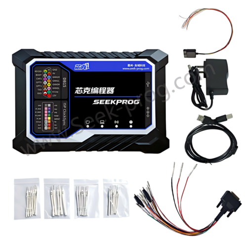
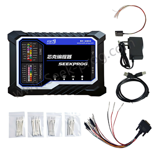
SeekProg for Professional Chip Programming
SeekProg is designed as a professional chip programming solution for automotive electronics and supports multiple programming protocols used with different chip and processor families.
Its multi-protocol approach is intended to help automotive technicians work with a broader range of electronic components instead of relying on a single programming interface.
For workshops working with ECU repair, chip programming, module cloning and automotive electronic service, selecting equipment with appropriate protocol coverage can provide greater flexibility for different repair jobs.
Common Mistakes When Selecting a Protocol
Choosing a Protocol Based Only on the ECU Brand
The ECU manufacturer does not always determine the programming protocol. The processor and memory architecture must also be considered.
Assuming Similar Chips Use the Same Pinout
Chips with similar packages can have different pin assignments. Always confirm the correct pinout for the exact component.
Ignoring Power Requirements
Programming interfaces may require specific power conditions. Always follow the supported connection procedure for the target device.
Using an Incorrect Device Profile
The programming software should match the exact chip or processor whenever the application requires device-specific settings.
Starting Without a Backup
When the original data can be read safely, technicians should save and verify the original data before modifying or writing the target component.
Professional Chip Programming Workflow
- Identify the vehicle and electronic module
- Identify the exact processor or memory chip
- Confirm the supported programming protocol
- Check the correct pinout
- Verify power and ground requirements
- Connect the programming equipment
- Read and save the original data when supported
- Verify the original data
- Perform the required programming operation
- Verify the programmed result
Best Practices for JTAG, SWD, BDM, SPI and I2C Programming
- Identify the exact chip before selecting a protocol
- Confirm the processor or memory manufacturer
- Check the exact chip model
- Use the correct pinout
- Verify power and ground connections
- Follow the supported programming procedure
- Back up original data whenever possible
- Keep original and modified files separately
- Verify the programming result
- Do not substitute one protocol for another without confirmed device support
Conclusion
JTAG, SWD, BDM, SPI and I2C are different programming and communication interfaces used across a wide range of electronic components. Each protocol has its own applications, connection requirements and supported device architectures.
For professional automotive electronics technicians, the most important step is accurate component identification. Once the exact processor or memory device is known, the appropriate programming protocol and connection method can be selected.
A multi-protocol chip programmer provides greater flexibility for workshops that handle different ECU architectures, memory devices and automotive electronic modules.
Understanding the differences between JTAG, SWD, BDM, SPI and I2C helps technicians build a more reliable chip programming workflow and select the correct interface for each supported repair operation.