
Automotive ECU Clock Circuit Diagnosis: Crystal Oscillator Testing and Repair
Automotive electronic control units rely on microcontrollers and other digital components to process signals, execute software and communicate with vehicle systems. For these operations to function correctly, the electronic circuitry must receive a suitable timing reference.
Depending on the ECU architecture, this timing reference may come from a crystal oscillator, a ceramic resonator, an external clock generator or an integrated oscillator circuit.
When a clock circuit fails or becomes unstable, the ECU may exhibit symptoms such as failed startup, missing communication, intermittent operation or an inability to perform certain functions. These symptoms can resemble processor failure, corrupted software or a power supply problem.
For automotive electronics technicians, understanding ECU clock circuit diagnosis helps narrow the possible causes before replacing expensive components or attempting unnecessary programming operations.
This guide explains how ECU clock circuits work, how to identify common oscillator components, which symptoms may indicate a timing problem, and how to approach clock circuit inspection and verification safely.
1. What Is an ECU Clock Circuit?
A clock circuit provides timing information that allows digital electronic components to coordinate their operations. In an ECU, this timing reference may be used by a microcontroller, communication interface or other digital circuitry.
The clock source and its supporting circuitry depend on the specific controller design. Some microcontrollers contain internal oscillators, while others use an external crystal, resonator or dedicated clock source.
Depending on the architecture, the clock system may support:
- Microcontroller instruction execution.
- Timing coordination between internal circuit blocks.
- Communication interfaces and peripheral functions.
- Time-dependent measurements and control operations.
- Synchronization between selected digital components.
Not every clock signal performs all these functions, and not every ECU uses the same oscillator arrangement.
Before diagnosing a suspected clock fault, identify the microcontroller and obtain the relevant circuit information whenever possible.
2. Understand Crystal Oscillators and Resonators
Crystal oscillators and resonators are used in electronic circuits to establish a timing reference. Although they can look similar, their electrical characteristics and circuit requirements may differ.
Quartz crystal
A quartz crystal is a passive frequency-selective component. It typically operates with an oscillator circuit that supplies the required electrical conditions for oscillation.
In an ECU, the crystal may be connected to dedicated oscillator pins on the microcontroller or another integrated circuit.
The crystal itself does not necessarily generate a usable clock output independently. The surrounding circuit and the device's oscillator design are important parts of the system.
Ceramic resonator
A ceramic resonator can provide a timing reference in suitable electronic designs. Its characteristics differ from those of a quartz crystal, including frequency tolerance and other electrical properties.
A replacement must match the requirements of the original circuit. A component that looks similar may not be electrically interchangeable.
Integrated oscillator
Some microcontrollers contain an internal oscillator or support multiple clock sources. In these designs, a visible external crystal may not be present or may serve a different purpose.
The correct diagnostic approach therefore begins with identifying the actual clock architecture rather than assuming every ECU contains the same type of oscillator.
3. Common Symptoms of ECU Clock Circuit Problems
A clock circuit fault can affect digital operation, but its symptoms are not unique to oscillator failure.
Possible symptoms include:
- The ECU fails to initialize under otherwise appropriate conditions.
- Communication with diagnostic or programming equipment is unavailable.
- The controller starts intermittently.
- The ECU becomes unreliable after temperature changes.
- A particular digital function stops operating correctly.
- The controller repeatedly resets or fails to complete initialization.
- Programming or identification attempts fail despite correct connections.
These symptoms may also result from power supply faults, defective reset circuitry, damaged communication interfaces, microcontroller failure or other internal defects.
Do not diagnose a crystal oscillator as defective based solely on a communication error or an ECU that does not respond.
4. Step One: Verify the ECU Power Supply and Reset Conditions
Before investigating the clock circuit, confirm that the ECU receives the required power and ground connections.
A microcontroller may fail to start even when its clock source is functioning correctly if its supply voltage, reset signal or required enable conditions are incorrect.
Depending on the ECU design, initial checks may include:
- Permanent and switched power supplies.
- Ground connection integrity.
- Voltage stability under the specified operating conditions.
- Reset circuit components and relevant signals.
- Required startup or activation conditions.
- Visible damage around the power management section.
Use the applicable wiring diagram and technical documentation. Different ECUs can use different reset arrangements, supply voltages and startup sequences.
If a supply or reset fault is identified, investigate it before drawing conclusions about the oscillator.
5. Step Two: Identify the Clock Source on the PCB
Once the basic electrical conditions have been evaluated, identify the suspected clock components on the circuit board.
Useful information includes:
- Microcontroller manufacturer and complete part number.
- PCB reference designators and component markings.
- Available schematic or board layout.
- Oscillator frequency specified by the design.
- Relevant microcontroller datasheet information.
- Clock source and startup requirements, where documented.
Crystal and resonator packages vary in size, shape and marking. Some contain limited identification information, so visual appearance alone may not establish the exact frequency or component specification.
Trace the circuit using the available documentation and identify the relevant microcontroller pins before taking measurements.
Avoid probing unidentified terminals or assuming that every small component near a microcontroller is part of its clock circuit.
6. Step Three: Inspect the Clock Circuit Visually
A visual inspection can reveal some problems without requiring direct measurements of sensitive oscillator pins.
Inspect the relevant PCB area for:
- Cracked or physically damaged oscillator packages.
- Corrosion around component terminals.
- Damaged solder joints.
- Missing or damaged supporting capacitors.
- PCB trace damage.
- Signs of overheating or liquid exposure.
- Previous rework or incorrect component replacement.
Use suitable magnification and lighting when examining small components and solder joints.
A component that appears normal may still be electrically defective. Conversely, discoloration or surrounding contamination does not automatically prove that the oscillator is the cause of the ECU fault.
Document the original condition before performing any rework, particularly when the controller has already been repaired by another technician.
7. Step Four: Understand the Role of Supporting Components
A clock circuit may contain more than a crystal or resonator. Depending on the design, its operation can also depend on capacitors, resistors, internal oscillator amplifiers and the microcontroller itself.
Potential fault areas include:
- Damaged or incorrect load capacitors.
- Open or shorted supporting components.
- Corroded PCB traces or component pads.
- Defective oscillator circuitry inside the microcontroller.
- Incorrect replacement component characteristics.
- Contamination affecting high-impedance circuit nodes.
The required component values and circuit configuration depend on the original design. Do not select replacement capacitors or resistors by visual similarity alone.
Where a schematic is unavailable, use verified component markings, device documentation and careful circuit analysis rather than making unsupported assumptions about the original values.
8. Step Five: Decide Whether Clock Signal Measurement Is Appropriate
Direct clock measurement may help establish whether an oscillator is operating, but the measurement method must be suitable for the circuit.
Some oscillator nodes are sensitive to additional capacitance and probe loading. Connecting an unsuitable test probe can alter the oscillation or cause the circuit to stop operating.
Before measuring a clock signal, establish:
- The expected signal frequency or operating range.
- The appropriate measurement point.
- The permitted voltage range.
- The required probe impedance and capacitance.
- The measurement equipment's bandwidth and input characteristics.
- The ECU's required power and startup conditions.
Depending on the circuit, a suitable oscilloscope probe or another manufacturer-recommended measurement method may be required.
A conventional multimeter is generally not sufficient to establish the detailed waveform and startup behavior of a high-frequency clock signal.
Never connect a grounded oscilloscope probe to an unknown circuit node without understanding the grounding arrangement. An incorrect connection can create a short circuit or damage the ECU.
9. Step Six: Interpret Clock Measurements Carefully
Clock measurements must be compared with the correct circuit specifications and operating conditions.
Possible findings include:
- No observable oscillation at the expected measurement point.
- An unstable or intermittent waveform.
- A frequency that does not match the documented requirement.
- A signal that changes unexpectedly during startup.
- A measurement that changes when the probe is connected.
These findings do not automatically identify a defective crystal. The cause may involve the oscillator amplifier, supporting components, power supply, reset conditions or the microcontroller itself.
Likewise, an apparently correct waveform at one point does not establish that every internal clock domain or peripheral is functioning correctly.
Use the circuit documentation to determine what the measurement proves and which parts of the clock system remain unverified.
10. Step Seven: Investigate Temperature-Related or Intermittent Faults
Some electronic faults become apparent only under particular temperature or operating conditions. An oscillator circuit can be affected by component deterioration, poor solder joints or changes in circuit behavior.
When a fault is intermittent, record the conditions under which it occurs.
Useful observations include:
- Whether the ECU starts consistently from a cold condition.
- Whether the problem appears after the controller warms up.
- Whether communication drops after a period of operation.
- Whether the fault changes after a previous repair.
- Whether the supply voltage or reset behavior changes at the same time.
Use appropriate controlled testing methods and avoid excessive heating or cooling of individual components. Uncontrolled temperature changes can damage the PCB, seals and nearby components.
Do not conclude that an oscillator is defective merely because the symptom changes with temperature. Other semiconductor devices, connectors and solder joints can produce similar behavior.
11. Step Eight: Replace an Oscillator Only When the Evidence Supports It
When testing confirms that an oscillator component is defective, select a replacement compatible with the original circuit.
Verify the relevant characteristics, which may include:
- Nominal frequency.
- Frequency tolerance and stability requirements.
- Load capacitance, where applicable.
- Equivalent series resistance, where relevant.
- Drive level and oscillator circuit compatibility.
- Package dimensions and terminal arrangement.
- Operating temperature range.
These characteristics are not identical for all clock components. Use the original component specifications and the microcontroller manufacturer's recommendations when selecting a replacement.
A crystal with the same nominal frequency may still be unsuitable if its other electrical characteristics do not match the oscillator circuit.
Follow appropriate ESD precautions and use controlled electronic rework techniques. Avoid excessive heat, lifted PCB pads and damage to nearby components.
12. Step Nine: Verify the Clock Circuit After Repair
After replacing a component or repairing a suspected clock circuit fault, repeat the relevant checks under the same conditions used during the initial diagnosis.
Depending on the circuit, verification may include:
- Inspecting the repaired area under magnification.
- Checking solder joints and adjacent components.
- Confirming that no unintended shorts remain.
- Verifying the required power and reset conditions.
- Checking the clock behavior using an appropriate method.
- Confirming that the ECU initializes as expected.
- Testing communication with supported diagnostic or programming equipment.
- Completing relevant functional tests.
If the original symptom persists, continue the diagnostic process instead of repeatedly replacing components.
The clock circuit may be functioning while another part of the ECU remains defective. Final verification should establish whether the original problem has been resolved, not simply whether a replacement component has been installed.
13. When Should ECU-Level Programming Be Considered?
A clock circuit fault is primarily an electronic hardware diagnosis. Reprogramming the ECU is not a universal solution for a controller that fails to start or communicate.
Programming may be relevant when the evidence indicates a separate supported software or memory problem. Before beginning, establish whether the ECU can communicate, whether the required programming method is supported and whether the electrical conditions are suitable.
If the microcontroller cannot initialize because of a hardware fault, a normal programming operation may not be possible until that fault is addressed.
Where programming is appropriate, preserve available original data and follow the exact procedure for the controller and target device.
SeekProg's ECU Identification Before Programming Guide explains why accurate controller identification is important before selecting a programming method.
Common ECU Clock Circuit Diagnosis Mistakes
Assuming Every Communication Failure Is an Oscillator Fault
Communication problems can result from incorrect power, reset circuitry, network wiring, interface damage or other ECU faults. Verify the basic operating conditions first.
Replacing a Crystal Based Only on Its Appearance
Visual inspection cannot establish whether a crystal has the correct electrical characteristics or whether it is functioning correctly. Confirm the component identity and use appropriate tests.
Measuring Sensitive Oscillator Pins With Unsuitable Equipment
Probe loading can affect some oscillator circuits. Select a measurement method that is appropriate for the signal and circuit design.
Ignoring Supporting Components
Capacitors, resistors, solder joints and internal oscillator circuitry can all affect clock operation. Diagnose the complete circuit rather than assuming the crystal is the only possible failure point.
Replacing Components Without Confirming the Original Fault
Unnecessary rework can introduce additional problems. Establish the evidence supporting a component replacement before removing it.
Assuming a Working Clock Proves the Entire ECU Is Healthy
A verified clock signal does not establish that the processor, memory, reset logic, communication interfaces and other circuits are all functioning correctly.
ECU Clock Circuit Diagnosis Checklist
- ECU part number and microcontroller identified.
- Original symptoms and communication status recorded.
- Power supply and ground conditions checked.
- Reset and startup conditions investigated where appropriate.
- Clock source identified from reliable technical information.
- Oscillator and surrounding components inspected.
- Supporting components and PCB connections evaluated.
- Measurement equipment selected for the circuit requirements.
- Clock measurements compared with documented specifications.
- Replacement component compatibility confirmed before rework.
- Post-repair electrical checks completed.
- ECU initialization and communication verified.
- Original symptoms reassessed and final results documented.
Frequently Asked Questions
Can a faulty crystal oscillator prevent an ECU from communicating?
Yes. If the affected clock source is required for microcontroller operation or a relevant communication function, a clock circuit fault may prevent normal operation. However, communication failure can also have many other causes.
Can I test an ECU crystal with a multimeter?
A multimeter may help with selected supporting-circuit checks, but it generally cannot provide a complete assessment of oscillator frequency, waveform quality or startup behavior. Use an appropriate method based on the circuit design.
Can I replace an ECU crystal with one that has the same frequency?
Not necessarily. Other characteristics, such as load capacitance, stability, drive requirements and package configuration, may also need to match the original design.
Why does an ECU work when cold but fail when warm?
Temperature-related failure may involve semiconductor devices, solder joints, connectors, oscillator circuitry or other components. Reproduce the fault under controlled conditions and compare the relevant measurements before identifying the cause.
Does an ECU that cannot be identified by a programmer have a clock fault?
Not necessarily. Check power, ground, reset conditions, wiring, communication setup and supported programming methods before investigating the clock circuit as a possible cause.
Should I reprogram an ECU if the clock signal is missing?
Not as the first response. Establish why the clock is missing and whether the microcontroller can initialize. A hardware fault may need to be corrected before supported programming operations can proceed.
SeekProg Resources for Automotive Chip Diagnosis
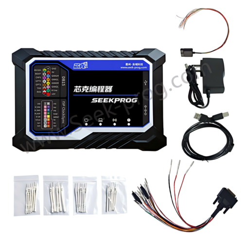
SeekProg provides chip programming equipment and technical resources for automotive electronics service. When a suspected ECU clock fault leads to further chip-level investigation, accurate device identification and a suitable diagnostic method remain essential.
- SeekProg Official Website — explore chip programming equipment and technical resources.
- Automotive MCU and Memory Chip Identification Guide — learn how to identify target semiconductor devices before selecting an operation.
- Chip Programming Workflow Explained — understand device identification, programming and result verification.
- Automotive ECU PCB Inspection Guide — review PCB inspection methods for visible component and circuit damage.
- EEPROM Programming Guide for Automotive ECU Repair — learn about supported memory operations and data verification.
Programming support varies by device, hardware revision and intended operation. Confirm the exact component and supported functions before connecting programming equipment or attempting to modify memory.
Conclusion
ECU clock circuits provide the timing references required by microcontrollers and other digital components. When these circuits fail, an ECU may exhibit startup problems, unstable behavior or communication failures that resemble other hardware or software faults.
Reliable diagnosis begins with checking the power supply and reset conditions, identifying the actual clock architecture and inspecting the oscillator and its supporting components. Direct signal measurements should use suitable equipment and be interpreted against the correct technical specifications.
When component replacement is justified, verify the replacement's electrical characteristics and complete the required post-repair checks. If the original fault persists, continue investigating the ECU rather than assuming the clock component was the only possible cause.
Professional safety notice: ECU clock circuit diagnosis and component-level repair should be performed by qualified technicians using appropriate ESD precautions, verified technical documentation and suitable measurement equipment. Incorrect probing, unsuitable replacement components or uncontrolled rework can damage sensitive electronic circuits.