
Automotive CAN Bus Transceiver Diagnosis: ECU Communication Faults and Repair
Modern vehicles rely on communication networks to exchange information between electronic control units. Engine control units, transmission controllers, body control modules, instrument clusters and other electronic systems may communicate through a Controller Area Network (CAN) or other vehicle network technologies.
When a vehicle develops communication problems, the cause may be related to wiring, connectors, power supply, grounding, network termination or an electronic component inside one of the connected modules. In some cases, a defective CAN bus transceiver can prevent an otherwise functional controller from communicating correctly.
Replacing an ECU without identifying the actual fault can increase repair costs and introduce additional compatibility problems. A structured diagnostic process helps technicians determine whether the problem originates in the vehicle network, the ECU's internal communication circuitry or another component.
This guide explains how automotive CAN transceivers work, which symptoms may indicate a hardware fault, how to investigate CAN-H and CAN-L signals, and what to check before replacing a suspected defective component.
What Is an Automotive CAN Bus Transceiver?
A CAN transceiver is an electronic interface between a controller's digital communication signals and the physical CAN bus. It converts logic-level signals into differential bus signals and translates received bus activity back into signals that the controller can process.
In a typical CAN communication system, the microcontroller or CAN controller manages communication logic, while the transceiver provides the electrical interface to the network.
These functions are related but different. A communication problem may originate in the transceiver, the controller, the wiring or the software configuration.
Depending on the design, a CAN transceiver may provide functions such as:
- Transmitting differential signals onto CAN-H and CAN-L.
- Receiving communication signals from the CAN bus.
- Supporting specified communication speeds.
- Providing protection against certain electrical disturbances.
- Supporting standby, sleep or wake-up functions.
- Supporting particular CAN network implementations, including compatible CAN FD applications.
Not every transceiver supports every feature. The exact capabilities depend on the component model and the electronic system in which it is installed.
Why CAN Transceiver Faults Matter in ECU Repair
An ECU may have functioning internal memory and a working processor but still fail to communicate with diagnostic equipment or other vehicle modules if its physical network interface is defective.
A damaged transceiver may interrupt transmission, prevent reception or electrically disturb the communication network.
Possible consequences include:
- Loss of communication with one electronic control unit.
- Intermittent communication between vehicle modules.
- Multiple network-related diagnostic trouble codes.
- Abnormal CAN-H or CAN-L signal behavior.
- A communication line that appears shorted or held in an abnormal state.
- Unexpected network disruption when a particular module is connected.
These symptoms do not prove that the transceiver is defective. A damaged harness, poor ground, faulty power supply, another module or a network configuration issue can produce similar behavior.
Before replacing a component, establish whether the fault is associated with the physical network, the ECU's power supply or the internal communication interface.
Step 1: Identify the Affected ECU and Communication Network
Begin by identifying the vehicle, the affected electronic controller and the communication network involved in the fault.
Record the available information, including:
- Vehicle manufacturer, model and production year.
- ECU manufacturer and complete part number.
- Hardware number and revision.
- Communication-related diagnostic trouble codes.
- Whether one module or multiple modules are unavailable.
- Whether the problem is permanent or intermittent.
- Any recent battery, wiring, ECU or electronic accessory work.
Use the correct wiring diagram to identify the network connected to the affected module. A vehicle may contain several CAN networks operating at different speeds or serving different functions.
Do not assume that every communication fault belongs to the same CAN network. Some vehicles use gateways, multiple network segments or other communication technologies.
Identifying the correct network helps prevent unnecessary testing of unrelated circuits.
Step 2: Understand the Difference Between a CAN Controller and a Transceiver
Before investigating a suspected communication chip, it is important to distinguish the CAN controller from the CAN transceiver.
CAN Controller
The CAN controller handles communication-related logic, including message processing and protocol functions. Depending on the system, it may be integrated into the main microcontroller or implemented as a separate device.
CAN Transceiver
The transceiver provides the electrical connection between the controller's digital interface and the physical CAN bus. It handles the differential signaling used by the network.
A fault in either component can interrupt communication, but the diagnostic approach may differ.
For example, an ECU with a defective transceiver may fail to drive or receive bus signals correctly. A problem in the controller, clock system or internal processor may prevent communication even if the transceiver itself is functional.
Accurate component identification is therefore essential before attempting board-level repair.
Step 3: Check ECU Power Supply and Ground Connections
Power supply and grounding problems should be investigated before concluding that a CAN transceiver has failed.
An ECU may become unavailable if its supply voltage falls outside the required range or if its ground connection develops excessive resistance.
Inspect the relevant circuits for:
- Blown fuses or interrupted power supply circuits.
- Loose or corroded connectors.
- Damaged ground conductors.
- Excessive voltage drop under the specified operating conditions.
- Unstable supply voltage.
- Damaged PCB power regulation components.
Follow the manufacturer's electrical testing procedure and compare measurements with the specifications for the target ECU.
If the controller has an internal power supply fault, replacing the CAN transceiver alone may not restore communication.
Step 4: Inspect CAN-H and CAN-L Wiring
High-speed CAN networks commonly use two differential signal lines, CAN-H and CAN-L. Their electrical relationship allows the receiving circuitry to distinguish dominant and recessive bus states.
Before testing the ECU itself, inspect the relevant vehicle wiring and connectors.
Look for:
- Damaged or pinched communication wires.
- Corrosion at connector terminals.
- Loose or recessed pins.
- Short circuits between CAN-H and CAN-L.
- Short circuits to power or ground.
- Incorrect repairs or unauthorized wiring modifications.
- Damage near the ECU connector or previous repair locations.
A wiring fault can produce the same symptoms as a defective transceiver. If the network is shorted externally, a functioning ECU may appear unable to communicate.
Where possible, compare the affected circuit with the manufacturer's wiring diagram and isolate the relevant network segment according to the service procedure.
Step 5: Understand CAN Bus Voltage and Signal Behavior
On a typical high-speed CAN network, CAN-H and CAN-L carry complementary differential signals.
When the bus is in the recessive state, both lines are commonly near 2.5 V relative to the relevant circuit ground. During a dominant state, CAN-H typically rises toward approximately 3.5 V while CAN-L falls toward approximately 1.5 V.
These values are illustrative rather than universal limits. Actual measurements depend on the transceiver, network architecture, operating state, measurement location and vehicle-specific design.
For a meaningful diagnosis, technicians should determine whether:
- The network shows activity when communication is expected.
- The two signal lines exhibit the expected differential behavior.
- One line is unexpectedly held at a fixed voltage.
- The signals show excessive noise or distortion.
- The waveform changes when the affected module is connected or disconnected under an approved procedure.
A digital multimeter can provide useful voltage information, but it may not reveal brief communication pulses or waveform distortion. An oscilloscope or suitable automotive network analyzer can provide more detailed information.
Use the correct reference ground and measurement procedure. Avoid probing unidentified terminals or shorting adjacent pins with test leads.
Step 6: Check CAN Bus Termination Correctly
CAN networks commonly use termination resistors to control signal reflections. In a conventional high-speed CAN segment with two 120-ohm terminators connected in parallel, the expected resistance across CAN-H and CAN-L is approximately 60 ohms when measured under the appropriate unpowered conditions.
However, this value is not appropriate for every vehicle network or every measurement state. Some systems use different topologies, split termination, switched termination or additional network components.
Before measuring resistance:
- Follow the manufacturer's power-down and isolation procedure.
- Confirm the exact network segment being tested.
- Identify the location of the termination resistors.
- Disconnect or isolate components only as specified.
- Compare the measurement with the applicable service information.
An unexpected resistance reading may indicate an open circuit, short circuit, missing termination or a measurement taken under unsuitable conditions.
Do not replace a CAN transceiver simply because the measured resistance differs from an assumed universal value. Establish the correct expected value for the specific network first.
Step 7: Identify the CAN Transceiver on the ECU PCB
If external wiring, power supply and network conditions have been checked, a closer inspection of the ECU circuit board may be appropriate.
Identify the suspected transceiver using its complete component marking and the relevant datasheet.
Useful information includes:
- Manufacturer and complete part number.
- Package type and pin count.
- Supply voltage requirements.
- Logic-side signal pins.
- CAN-H and CAN-L connections.
- Enable, standby or wake-up pins, where applicable.
- Supported communication mode and speed.
Do not identify a transceiver solely by its physical location or package shape. Similar-looking integrated circuits may serve different purposes and use different pin assignments.
The component datasheet and PCB circuit tracing should be used together to establish the correct device identity.
For more background on identifying semiconductor devices before electronic repair, see the Automotive MCU and Memory Chip Identification Guide.
Step 8: Inspect the Transceiver and Surrounding Circuit
Once the target component has been identified, inspect the surrounding circuit for physical damage or conditions that may affect its operation.
Potential issues include:
- Corrosion or contamination around component pins.
- Cracked solder joints.
- Burned or discolored PCB areas.
- Damaged protective components on the CAN lines.
- Shorted capacitors or other components connected to the interface.
- Damaged PCB traces or vias.
- Previous soldering or repair damage.
A CAN interface may include protection devices and supporting components in addition to the transceiver itself. A failed protection component can affect the bus even if the transceiver is functional.
Where suitable equipment and documentation are available, use electrical measurements to investigate the relevant circuit rather than replacing components based only on appearance.
If the PCB has suffered water damage or an electrical surge, inspect the surrounding circuitry before assuming that a single chip is responsible for the fault.
Step 9: Determine Whether the Transceiver Is Actually Defective
Replacing a CAN transceiver should be based on diagnostic evidence rather than the presence of communication trouble codes alone.
Evidence that may support further transceiver investigation includes:
- Verified ECU power and ground conditions.
- Correct external CAN wiring and network conditions.
- Abnormal signal behavior associated with the affected ECU.
- Evidence of a shorted or damaged interface component.
- Electrical measurements inconsistent with the identified device's requirements.
- Reliable evidence that the fault is localized to the ECU's communication interface.
No single observation proves a defective transceiver in every situation. A processor fault, damaged PCB trace or another component may produce similar behavior.
Where the fault cannot be isolated confidently, continue with the appropriate circuit-level diagnosis before replacing the component.
Step 10: Replace the Transceiver When Repair Is Justified
If testing confirms that a transceiver is defective and replacement is appropriate, select a compatible component and follow a suitable electronic rework procedure.
Before removing the original component, verify:
- The complete part number and package.
- Electrical and communication compatibility.
- Pin arrangement and component orientation.
- Availability of a suitable replacement.
- Whether the replacement supports the required CAN implementation.
- Any relevant PCB repair or manufacturer requirements.
Some transceivers support specific features such as CAN FD, low-power operation or wake-up functions. A component with a similar appearance is not necessarily a suitable substitute.
During rework, use appropriate ESD precautions and equipment suitable for the component and PCB construction. Avoid excessive heat, mechanical force and solder bridges between adjacent pins.
After removal, inspect the pads and surrounding traces before installing the replacement. If the board has sustained additional damage, address those faults as part of the repair.
Step 11: Verify CAN Communication After Repair
After a suspected transceiver fault has been repaired, confirm that the communication network operates correctly under the required conditions.
The verification process may include:
- Inspecting the replaced component and solder joints.
- Checking the ECU's power and ground connections.
- Confirming that the CAN-H and CAN-L wiring is correctly connected.
- Checking the network's electrical behavior.
- Establishing communication with the repaired ECU.
- Scanning relevant modules for diagnostic trouble codes.
- Confirming that communication faults do not return under the specified test conditions.
- Recording the repair and final test results.
A controller that responds to diagnostic equipment may still have an intermittent fault. Where the original problem was intermittent, complete the appropriate extended testing rather than relying solely on one successful communication attempt.
Likewise, successful communication does not prove that every ECU function is operating correctly. Complete the relevant system-level tests before returning the vehicle to service.
Common CAN Transceiver Diagnostic Mistakes
Replacing the ECU Before Checking the Wiring
External wiring faults can prevent a functioning controller from communicating. Inspect the network and verify its electrical conditions before condemning the ECU.
Assuming Every Communication Fault Is a Transceiver Fault
Power supply problems, damaged grounds, controller faults and network configuration issues can produce similar symptoms. Establish the fault location before replacing components.
Using an Incorrect Termination Resistance Expectation
Approximately 60 ohms is common for a conventional high-speed CAN segment with two parallel 120-ohm terminators, but vehicle network designs differ. Follow the relevant wiring diagram and service procedure.
Relying Only on a Multimeter
A multimeter can reveal useful voltage or resistance information, but it may not capture short-duration communication faults or distorted waveforms. Use suitable diagnostic equipment for the question being investigated.
Replacing a Similar-Looking Transceiver
Package appearance does not establish electrical compatibility. Verify the complete part number, pinout and required communication features.
Ignoring Protection Components
Components connected to the CAN lines may also affect communication. Inspect the surrounding interface circuit before concluding that the transceiver itself has failed.
Failing to Verify the Repair
Installing a replacement component does not establish that the network fault has been resolved. Complete communication, electrical and functional checks after repair.
CAN Transceiver Diagnosis Checklist
- Vehicle and affected ECU identified.
- Relevant communication network confirmed.
- Diagnostic trouble codes recorded.
- ECU power supply and ground checked.
- CAN-H and CAN-L wiring inspected.
- Connector condition and terminal retention checked.
- Network electrical conditions measured using the correct procedure.
- Termination requirements confirmed from technical documentation.
- Suspected transceiver identified by its complete part number.
- Surrounding protection components and PCB traces inspected.
- Fault localized before component replacement.
- Replacement compatibility verified.
- Rework quality inspected.
- Communication and post-repair checks completed.
How SeekProg Fits Into Automotive Chip-Level Repair
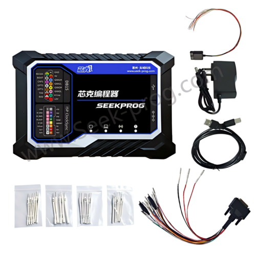
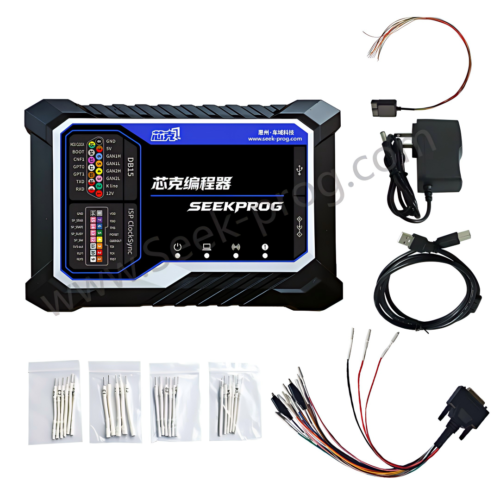
SeekProg is a chip programming solution for supported semiconductor devices used in automotive electronics and other electronic applications. Chip programming and CAN transceiver diagnosis are related parts of an electronics workshop's workflow, but they are not the same operation.
A CAN transceiver is generally a communication interface device, not a memory chip that needs its contents programmed during ordinary replacement. Diagnosing or replacing a defective transceiver typically requires electrical testing, component identification and appropriate PCB rework.
SeekProg's relevance depends on the actual programmable device involved in the wider repair. When a job also requires supported operations on an EEPROM, Flash memory device or microcontroller, technicians should confirm that the exact device and intended programming function are supported.
Useful preparation resources include:
- Automotive MCU and Memory Chip Identification Guide.
- JTAG, SPI, I2C, BDM and SWD Programming Guide.
- EEPROM Programming Guide for Automotive ECU and Electronic Module Repair.
- SeekProg Chip Programmer Product Page.
Always verify the exact semiconductor device, programming method and supported operation before connecting programming equipment.
Frequently Asked Questions
What does an automotive CAN transceiver do?
A CAN transceiver converts between the controller's digital communication signals and the differential electrical signals on the CAN bus. It provides the physical communication interface between the electronic controller and the network.
Can a defective CAN transceiver prevent an ECU from communicating?
Yes. A damaged transceiver can prevent normal transmission or reception and may interfere with the network. However, similar symptoms can be caused by wiring, power supply, grounding or other controller faults.
How can I tell whether a CAN transceiver is defective?
Begin by verifying ECU power, ground, wiring and network conditions. Inspect CAN signal behavior and the relevant PCB circuitry. A transceiver should only be condemned when the available diagnostic evidence supports that conclusion.
What is the normal resistance between CAN-H and CAN-L?
Approximately 60 ohms is common for a conventional high-speed CAN segment with two 120-ohm terminators in parallel when measured under the appropriate unpowered conditions. The expected value varies with network design, so always consult the vehicle-specific documentation.
Can a multimeter identify every CAN communication fault?
No. A multimeter can help check supply voltage, ground and selected resistance measurements, but an oscilloscope or suitable network analyzer may be needed to investigate signal timing, distortion or intermittent communication.
Can I replace a CAN transceiver with any chip in the same package?
No. The replacement must meet the required electrical, communication and functional specifications. Verify the full part number and datasheet rather than relying on package shape alone.
Does CAN transceiver replacement require chip programming?
Ordinary transceiver replacement generally involves hardware repair rather than programming the transceiver itself. However, separate ECU memory or microcontroller operations may be relevant to other parts of a repair when they are explicitly supported and required.
Conclusion
Automotive CAN transceiver diagnosis is an important part of investigating ECU communication failures. A defective interface chip can interrupt network communication, but similar symptoms can also result from external wiring, electrical supply problems, termination faults or other internal components.
A reliable repair process begins with identifying the affected network and ECU, checking power and ground connections, inspecting CAN-H and CAN-L wiring and measuring the relevant electrical conditions using the correct procedure.
Only after external causes have been evaluated should technicians focus on the transceiver and its surrounding circuitry. When component replacement is justified, compatibility checks and post-repair verification are essential.
By combining systematic network diagnosis with accurate component identification and appropriate electronic repair methods, automotive technicians can reduce unnecessary ECU replacement and improve the reliability of communication-related repairs.
Professional safety notice: Perform automotive electronic testing and PCB rework only with suitable equipment, verified technical documentation and appropriate electrical safety precautions. Follow the manufacturer's diagnostic procedures and confirm that the repaired vehicle communication system operates correctly before returning the vehicle to service.