
JTAG vs SPI vs I2C vs BDM vs SWD: Understanding Chip Programming Protocols
Modern automotive electronics contain many different microcontrollers, Flash memories, EEPROM devices and communication interfaces. Because different chips use different programming architectures, professional technicians may need several programming protocols when repairing or programming automotive electronic modules.
JTAG, SPI, I2C, BDM and SWD are five important protocols used in different types of chips and electronic systems. Understanding their basic differences helps technicians select the appropriate programming method for a supported ECU, dashboard, body control module, airbag module, battery system or other electronic controller.
This guide explains the characteristics of these five protocols and the factors that should be considered before starting a chip-level programming operation.
Why Multiple Chip Programming Protocols Are Needed
There is no universal programming interface that works with every automotive chip.
Different manufacturers and processor families use different architectures, communication interfaces and programming methods. A workshop working with multiple generations of automotive electronics may therefore encounter several protocols during normal repair work.
The required protocol depends on the exact chip or microcontroller, not simply on the vehicle brand.
For example, two ECUs from the same vehicle manufacturer may use completely different processors and require different programming connections.
What Is JTAG?
JTAG is a widely used interface for testing, debugging and programming supported processors and integrated circuits.
JTAG can provide relatively deep access to a supported processor and may be used for programming Flash, debugging hardware or performing other service operations depending on the device architecture.
In automotive electronics, JTAG can be encountered on selected ECUs, microcontrollers and other electronic modules.
The exact JTAG connection and available operations depend on the target device.
What Is SPI?
SPI stands for Serial Peripheral Interface.
SPI is commonly used for communication between a controller and external memory or other peripheral devices.
In automotive electronics, SPI memory devices can be found in different types of control modules and electronic boards.
A typical SPI connection uses several signal lines, commonly including clock, data input, data output and chip select.
The exact pin arrangement and voltage requirements depend on the specific device.
What Is I2C?
I2C stands for Inter-Integrated Circuit.
I2C is a serial communication protocol designed for communication between integrated circuits using a shared bus structure.
I2C devices commonly use two main signal lines:
- SDA for data
- SCL for clock
I2C can be found in various memory devices, sensors and other electronic components.
In automotive repair, the exact device and circuit configuration must be identified before attempting to access an I2C memory component.
What Is BDM?
BDM stands for Background Debug Mode.
BDM is associated with selected processor families and provides a method for debugging and programming compatible microcontrollers.
BDM has been used in various automotive electronic control units, particularly in certain older processor architectures.
The exact BDM connector, pin arrangement and available operations depend on the processor and ECU design.
What Is SWD?
SWD stands for Serial Wire Debug.
SWD is a debugging and programming interface commonly associated with supported ARM-based microcontrollers.
Compared with interfaces that use a larger number of dedicated debug signals, SWD can provide processor access through a relatively small number of connections.
Depending on the target microcontroller, SWD can be used for programming, debugging and other supported service operations.
JTAG vs SPI vs I2C vs BDM vs SWD
| Protocol | Typical Application | Common Target | Main Consideration |
|---|---|---|---|
| JTAG | Programming and debugging | Supported processors and integrated circuits | Requires the correct processor-specific connection |
| SPI | Memory and peripheral communication | Supported Flash and EEPROM devices | Correct chip identification and pinout are essential |
| I2C | Memory and peripheral communication | Supported EEPROM and other I2C devices | Device address and bus configuration must be considered |
| BDM | Processor programming and debugging | Supported processor families | Applicable mainly to compatible architectures |
| SWD | Programming and debugging | Supported ARM-based microcontrollers | Correct SWD connection and target support are required |
Which Protocol Should a Technician Use?
The correct protocol should always be selected according to the exact chip or ECU support information.
Do not choose a protocol simply because it is familiar or because another ECU uses the same vehicle manufacturer.
A professional selection process should begin with the electronic hardware itself.
- Identify the ECU or electronic module
- Record the hardware information
- Identify the processor or memory device
- Check the supported programming protocol
- Confirm the available Read and Write functions
- Review the connection diagram
- Verify voltage and pin orientation
- Perform the supported programming operation
Processor Identification Is Important
The processor is one of the most useful pieces of information when selecting a chip programming method.
Different processor families can use different programming interfaces.
For example, one ECU may use an ARM-based microcontroller with SWD support, while another controller may use a processor designed for JTAG or BDM access.
The processor name alone is still not always enough. The complete ECU hardware, board design and supported programming procedure must also be confirmed.
Memory Chip Identification
When working with external memory, technicians should identify the actual memory device before connecting a programmer.
Useful information includes:
- Chip manufacturer
- Chip part number
- Memory type
- Memory capacity
- Voltage requirement
- Communication protocol
- Package type
Two memory chips can have similar physical packages while using different communication protocols or electrical requirements.
Always confirm the exact device before applying a programming voltage.
SPI Programming Considerations
SPI programming requires careful identification of the memory device and its connection.
Before starting, confirm:
- Chip orientation
- Pin 1 position
- Power supply
- Ground
- Clock line
- Data input
- Data output
- Chip select
Depending on the circuit, the memory may remain connected to other components on the PCB. In-circuit programming can therefore require additional consideration because other components may influence the communication bus.
I2C Programming Considerations
I2C programming requires attention to both the physical connection and the bus configuration.
Before accessing an I2C device, confirm:
- SDA connection
- SCL connection
- Power
- Ground
- Device address
- Memory organization
- Voltage level
Incorrect device identification can result in failed communication or incorrect data access.
JTAG Programming Considerations
JTAG operations are normally more closely related to the target processor and its debug architecture.
Technicians should confirm:
- Processor family
- JTAG pin assignment
- Connector orientation
- Target voltage
- Required reset connection
- Programming software
- Supported memory operation
Board-level access requires particular attention to probe placement and pin orientation.
BDM Programming Considerations
BDM is associated with selected processor architectures and should only be used when the target processor and programming tool support the required operation.
Before connecting a BDM interface, verify:
- Processor family
- BDM connector or test points
- Pin 1 orientation
- Target voltage
- Reset requirements
- Supported programming functions
Do not assume that every older automotive ECU supports the same BDM connection.
SWD Programming Considerations
SWD is commonly used with supported ARM-based microcontrollers.
A typical SWD connection can involve a small number of dedicated signals, but the exact requirements depend on the target processor.
Verify:
- SWDIO
- SWCLK
- Ground
- Target voltage
- Reset when required
- Processor compatibility
Incorrect voltage or connection can prevent communication and may damage sensitive electronics.
Why Pinout Verification Matters
Knowing the correct protocol does not automatically mean that the wiring is correct.
The same protocol can be implemented differently across different boards.
Before powering the target device, verify:
- Connector orientation
- Pin numbering
- Signal names
- Power pins
- Ground pins
- Reset or control lines
- Target voltage
Use the exact connection information for the target ECU or chip.
In-Circuit Programming vs Chip-Level Access
Some memory devices can be accessed while they remain installed on the PCB, while other programming procedures may require the component to be isolated or removed.
The correct approach depends on the circuit design and the programming method.
Before attempting in-circuit programming, consider whether other components connected to the same communication lines could interfere with the operation.
If stable communication cannot be established, follow the supported hardware procedure instead of repeatedly attempting the same connection.
Protect Original Data Before Writing
Regardless of the programming protocol, original data should be preserved whenever the supported operation allows it.
Before writing new data:
- Read the original device when supported
- Save the original file
- Verify the read operation
- Create a separate working copy
- Confirm the target device
- Verify the programming file
- Perform the Write operation
The original backup should never be overwritten by a modified file.
Protocol Selection and ECU Repair
Chip-level programming can be useful during supported automotive electronic repair.
Depending on the module, technicians may encounter:
- Engine control units
- Transmission control units
- Body control modules
- Dashboard modules
- Airbag modules
- Battery control systems
- Other electronic controllers
The required protocol depends on the actual processor or memory device used by the module.
Therefore, a workshop that supports multiple automotive electronic systems benefits from a programming solution capable of working with multiple protocols.
Using SeekProg for Multi-Protocol Chip Programming
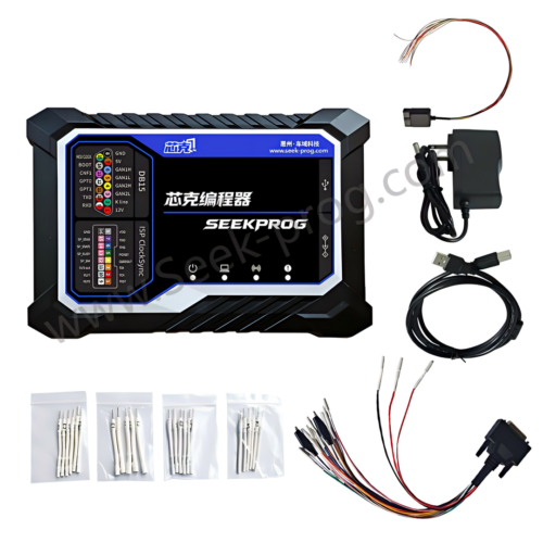
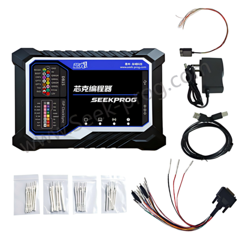
SeekProg is a professional chip programming solution designed for automotive electronic programming applications. Depending on the supported device and software function, the platform provides access to multiple programming protocols including JTAG, SPI, I2C, BDM and SWD.
This multi-protocol approach allows technicians to work with different types of chips, processors and automotive electronic modules without selecting a completely different programming platform for every protocol.
For supported applications, technicians should identify the exact chip or ECU first and then select the corresponding programming protocol and connection method provided by the software.
Learn more about the SeekProg Chip Programmer and its supported chip programming applications.
How to Build a Multi-Protocol Programming Workflow
A professional workshop can standardize its chip programming workflow regardless of which protocol is used.
- Identify the target ECU or chip
- Photograph the identification markings
- Record processor or memory information
- Determine the supported protocol
- Review the exact wiring diagram
- Verify power and ground
- Confirm target voltage
- Read and save original data when supported
- Verify the original file
- Prepare the working file
- Confirm the programming operation
- Write the target device
- Verify the programming result
- Save the final job record
Common Multi-Protocol Programming Mistakes
Choosing the Protocol by Vehicle Brand
The vehicle manufacturer does not determine the chip programming protocol by itself. Always identify the actual processor or memory device.
Using a Similar Chip as a Reference
A similar-looking chip does not guarantee identical memory organization, voltage requirements or communication protocol.
Ignoring Voltage Requirements
Chip-level electronics can be sensitive to incorrect voltage. Confirm the target requirements before applying power.
Connecting the Probe in the Wrong Orientation
JTAG, BDM and SWD interfaces can require precise orientation. Verify pin 1 and the complete connection before powering the board.
Skipping the Original Backup
When the device can be read successfully, save the original data before writing anything new.
Assuming One Protocol Works Everywhere
Different processors and memory devices require different interfaces. A multi-protocol workflow begins by identifying the target hardware correctly.
Protocol Selection Checklist
- Target ECU or module identified
- Chip manufacturer identified
- Chip part number recorded
- Processor identified
- Memory type identified
- Programming protocol confirmed
- Voltage requirement confirmed
- Pinout verified
- Connector orientation verified
- Original data backed up when supported
- Programming file verified
- Correct Read or Write function selected
- Programming result verified
- Final data stored securely
Frequently Asked Questions
What is the difference between JTAG and SWD?
Both can provide programming and debugging access to supported processors, but they are different interfaces with different signal configurations and target-device support.
What is the difference between SPI and I2C?
SPI and I2C are different serial communication protocols. SPI commonly uses separate clock, data and chip-select signals, while I2C uses a shared data and clock bus.
Is BDM still useful for automotive ECU programming?
BDM remains relevant for supported processor architectures found in certain automotive electronic controllers. Its usefulness depends on the target hardware.
Can one programming tool support multiple protocols?
Yes. A professional multi-protocol programmer can support multiple interfaces, allowing technicians to work with different processor and memory architectures through one platform when the exact devices are supported.
Should I select a protocol based only on the processor name?
No. The processor is an important identification reference, but the complete ECU or board hardware, memory architecture and supported programming procedure should also be confirmed.
Why should original chip data be backed up?
An original backup provides a reference before programming and can be important for supported repair, replacement, cloning or recovery procedures.
Conclusion
JTAG, SPI, I2C, BDM and SWD are different programming and communication interfaces used across a wide range of electronic devices. Automotive technicians can encounter these protocols when working with ECUs, TCUs, dashboards, body modules, airbag systems, battery controllers and other electronic equipment.
The most important principle is to identify the exact target device before selecting a protocol. Processor information, memory type, hardware revision, voltage requirements and the specific programming procedure should all be considered.
A multi-protocol programming solution can make a workshop more flexible by supporting different chip architectures through one programming platform. However, the correct protocol, connection diagram and programming function must always be confirmed for the exact target device.
With accurate identification, verified connections, protected original data and a controlled programming workflow, technicians can perform supported chip-level automotive electronic operations more efficiently and consistently.
Professional and authorized use notice: Chip and ECU programming should only be performed by trained technicians for lawful and authorized repair purposes. Available functions depend on the exact chip, processor, ECU hardware, software version and supported programming protocol.