Automotive Instrument Cluster Repair: Chip Programming, Data Backup and Replacement
Modern automotive instrument clusters are electronic systems that display vehicle speed, engine information, warning indicators, fuel level and other important operating data. Depending on the vehicle, the cluster may also communicate with other control units and store configuration or identification information.
When an instrument cluster develops an electronic fault, replacing the complete assembly is not always the only possible solution. Some problems originate from power supply circuits, communication networks, damaged components or memory devices that may be investigated as part of a professional electronic repair process.
Chip programming can support certain instrument cluster repair and replacement procedures when the target device, memory operation and programming method are supported. However, programming is only one part of the diagnostic process. Technicians must first identify the actual fault, protect original data and confirm the compatibility of the target component.
This guide explains the main considerations for instrument cluster chip programming, including MCU and EEPROM identification, data backup, replacement preparation and post-repair verification.
What Is an Automotive Instrument Cluster?
An automotive instrument cluster is the electronic assembly that presents vehicle information to the driver. Depending on the vehicle architecture, it may contain a display, gauges, indicator lights, a microcontroller, memory devices, communication interfaces and power management components.
Traditional instrument clusters may use electromechanical gauges and relatively simple electronic circuits, while modern digital clusters can incorporate more complex processors, displays and communication functions.
Common instrument cluster functions include:
- Displaying vehicle speed and engine speed.
- Presenting fuel level and temperature information.
- Displaying warning lights and diagnostic messages.
- Communicating with other electronic control units.
- Managing display settings and vehicle-specific configuration.
- Storing selected identification or configuration data, depending on the design.
The exact functions and memory architecture vary by manufacturer, vehicle generation and instrument cluster model. Technicians should identify the actual assembly rather than assuming that all dashboards use the same electronic design.
Common Instrument Cluster Problems
Instrument cluster symptoms can result from electrical faults, communication problems, damaged components, software issues or defective display hardware. Correct diagnosis is important because similar symptoms can have different causes.
1. The Display Does Not Turn On
A completely blank instrument cluster may indicate a power supply problem, a ground connection fault, a damaged circuit board or an internal electronic failure.
Before attempting chip programming, verify the relevant power and ground circuits, connectors and fuses using the appropriate vehicle wiring information.
2. Gauges Display Incorrect Information
Incorrect gauge readings can result from sensor faults, communication problems, configuration issues or faults within the cluster itself.
Compare available diagnostic information with the displayed readings to help determine whether the problem originates in the instrument cluster or another part of the vehicle.
3. Warning Indicators Behave Abnormally
Unexpected warning lights may be associated with stored diagnostic faults, missing communication, power interruptions or a defective cluster circuit.
Record the original symptoms and scan the relevant vehicle systems before deciding whether memory programming or hardware repair is necessary.
4. The Instrument Cluster Communicates Intermittently
Intermittent communication may be caused by damaged connectors, unstable power, wiring faults, network problems or an internal electronic defect.
Resolve external electrical and communication problems before assuming that the memory device or microcontroller requires programming.
5. The Cluster Fails After Replacement
A replacement instrument cluster may require compatible hardware, software, vehicle configuration or manufacturer-specific adaptation.
A module that physically fits the dashboard is not necessarily compatible with the vehicle. Confirm the correct application and supported replacement procedure before transferring data or installing the replacement.
MCU and EEPROM in Instrument Cluster Electronics
Instrument clusters can contain different semiconductor devices, including microcontrollers and non-volatile memory components. Understanding their roles helps technicians determine which components may be relevant to a particular repair.
Microcontrollers (MCUs)
A microcontroller integrates a processor with memory and peripheral functions. In an instrument cluster, it may execute the software responsible for display control, communication, input processing and other electronic functions.
Depending on the device, relevant data may reside in internal Flash, EEPROM-like memory, emulated EEPROM or other storage areas.
Programming access depends on the microcontroller architecture, supported interface and applicable security or service restrictions.
EEPROM and Other Non-Volatile Memory
Some instrument clusters use separate memory devices or dedicated non-volatile storage for configuration and other persistent information.
The actual data stored in these devices varies by manufacturer and cluster design. It should not be assumed that every EEPROM contains the same type of vehicle information.
Before reading or writing a memory device, identify its complete part number, capacity, package and electrical requirements. Confirm the supported programming method for the exact device.
Why Memory Identification Matters
A microcontroller and a standalone EEPROM are not interchangeable programming targets. They can require different adapters, programming algorithms, voltage conditions and connection methods.
For a more detailed explanation, read the Automotive MCU and Memory Chip Identification Guide.
Step 1: Identify the Instrument Cluster Before Repair
Accurate identification is the starting point for instrument cluster diagnosis and programming.
Record the following information whenever it is available:
- Vehicle make and model.
- Production year and relevant vehicle configuration.
- Instrument cluster manufacturer.
- Cluster part number and hardware revision.
- Software identification, where accessible.
- PCB revision, if the assembly is opened as part of an authorized repair.
- Processor and memory chip markings, when relevant.
- The original fault symptoms and diagnostic findings.
Photograph the cluster label and connectors before disassembly. If opening the assembly is necessary, document the original condition before cleaning, desoldering or modifying anything.
Do not select a programming profile based only on the vehicle model or the visual appearance of the cluster. Similar assemblies may use different processors, memory configurations or software.
Step 2: Diagnose the Fault Before Programming
Not every instrument cluster problem requires chip programming. A systematic diagnosis helps distinguish memory-related issues from external electrical faults and defective hardware.
Begin with a visual inspection and the relevant vehicle diagnostic procedure.
Check the following areas:
- Battery condition and electrical supply.
- Relevant fuses and ground connections.
- Cluster connectors and terminal condition.
- Communication with the instrument cluster.
- Related diagnostic trouble codes.
- Visible PCB damage, corrosion or overheating.
- Display and gauge behavior under appropriate test conditions.
If the cluster is not communicating, confirm its power supply and communication path before attempting a direct memory operation.
If the problem is caused by a damaged power regulator, broken trace or defective display component, rewriting memory data alone will not repair the underlying hardware fault.
Step 3: Determine Whether Chip-Level Access Is Required
After the initial diagnosis, determine whether the required repair can be performed through a supported diagnostic or programming connection or whether direct access to a memory device or microcontroller is necessary.
The appropriate approach depends on the cluster architecture and the operation being performed.
Potential considerations include:
- Whether the required data can be accessed through a supported diagnostic method.
- Whether the programming tool supports the exact cluster or chip.
- Whether direct chip access is required by the documented procedure.
- Whether the surrounding circuit affects in-circuit communication.
- Whether the original component can be read reliably.
- Whether a suitable replacement component is available if required.
Do not remove a chip simply because the cluster has developed a fault. Unnecessary desoldering introduces risks such as lifted pads, damaged traces and thermal damage.
Step 4: Back Up Original Data When Supported
When the target device and supported procedure allow reading, preserve the original data before performing a destructive operation or making modifications.
The original backup can provide a reference for comparison and may support an authorized recovery or replacement procedure.
A professional backup workflow includes:
- Confirm the exact memory device and programming profile.
- Verify the adapter and connection requirements.
- Check the required voltage and pin orientation.
- Perform the supported Read operation.
- Save the original file without modification.
- Record the device identification and file size.
- Verify the read result using the available functions.
- Store an additional protected copy where appropriate.
Do not assume that one memory read contains all the data required to restore or replace an instrument cluster. The required data areas depend on the specific module and repair procedure.
If repeated reads produce inconsistent results, investigate the connection, device selection and electrical conditions before relying on the file.
Step 5: Select the Correct Programming Method
Different instrument cluster components may require different programming interfaces. Depending on the supported device, a programming operation may involve SPI, I2C, JTAG, SWD, BDM or another interface specified by the manufacturer.
These interfaces serve different purposes and are not interchangeable simply because a programmer supports several of them.
Before connecting the programmer, verify:
- The complete chip part number.
- The supported programming interface.
- The correct pinout and connector orientation.
- Power and ground requirements.
- Required adapters or sockets.
- Whether in-circuit programming is supported.
- The exact Read, Write or other intended operation.
Use the chip manufacturer's documentation and the programming tool's current device support information. Never apply a connection diagram from a similar-looking component without verifying that it applies to the actual device.
Step 6: Understand In-Circuit and Out-of-Circuit Programming
Some memory devices can be accessed while they remain installed on the instrument cluster PCB. This is commonly described as in-circuit programming.
However, the surrounding circuit may interfere with communication or affect the electrical conditions required by the programming tool.
Out-of-circuit programming involves removing the component or otherwise isolating it from the surrounding circuit as required by the supported procedure.
| Consideration | In-Circuit Access | Out-of-Circuit Access |
|---|---|---|
| Component removal | Usually not required | Required when the chip must be physically removed |
| Connection complexity | Depends on PCB layout and accessible signals | Depends on chip package and adapter compatibility |
| Circuit interference | Possible | Reduced influence from the original PCB after removal |
| Rework risk | Lower risk from desoldering | Additional risk of heat damage or PCB pad damage |
| Best approach | When supported and communication is reliable | When isolation or removal is required by the procedure |
The correct method depends on the exact memory device and circuit design. Technicians should follow the supported procedure rather than assuming one approach is always preferable.
For additional technical background, see the EEPROM Programming Guide for Automotive ECU and Electronic Module Repair.
Step 7: Verify the Programming File
Before writing data to an instrument cluster, confirm that the file is appropriate for the target device and intended operation.
Check the following:
- File source and purpose.
- Target cluster or chip identification.
- Memory type and expected capacity.
- File format and structure.
- Expected file size.
- Compatibility with the selected programming function.
- Any applicable data integrity requirements.
A file that has the correct size may still belong to another device or contain incompatible data. Similarly, a file extension does not prove that its contents match the intended memory.
Keep the original backup unchanged and create a separate working copy when modifications are authorized and required.
Step 8: Understand Instrument Cluster Replacement
Replacing an instrument cluster involves more than matching the external dimensions and connectors.
Depending on the vehicle, the replacement may require manufacturer-specific configuration, initialization, coding or adaptation to other electronic systems.
Before installation, compare:
- Original and replacement part numbers.
- Hardware revisions.
- Supported vehicle application.
- Software compatibility.
- Display and equipment configuration.
- Manufacturer-required adaptation procedures.
- Relevant security and vehicle identification requirements.
Some replacement assemblies may be compatible with minimal setup, while others require additional service procedures.
Where data transfer is supported and authorized, confirm exactly which memory regions and configuration items are required. Do not assume that copying one chip or one file will reproduce every function of the original cluster.
Instrument Cluster Data Integrity and Odometer Records
Instrument clusters may display or store odometer information, depending on the vehicle architecture. These records require particular care during repair and replacement.
When servicing an instrument cluster, technicians should preserve the vehicle's genuine mileage information and maintain clear records of the original and replacement components.
Good professional practices include:
- Documenting the displayed mileage before repair when it is accessible.
- Recording the original and replacement cluster identification.
- Following the vehicle manufacturer's approved replacement procedure.
- Maintaining supporting repair records.
- Complying with applicable odometer, consumer protection and vehicle inspection laws.
Do not alter stored mileage to misrepresent vehicle use, conceal a replacement or mislead a buyer. Where mileage correction is legally permitted for a documented repair, follow the applicable legal and manufacturer requirements.
Odometer records should be treated as vehicle history information, not as an ordinary calibration setting.
Step 9: Verify the Cluster After Repair
After completing a supported programming or repair operation, perform the required checks before returning the vehicle to service.
A suitable verification process may include:
- Confirming that the instrument cluster powers on normally.
- Checking communication with the cluster and related control units.
- Reviewing diagnostic trouble codes.
- Verifying the expected display and indicator behavior.
- Checking supported gauges and available live data.
- Confirming required configuration or adaptation procedures.
- Checking that documented vehicle identification and mileage information remain consistent.
- Recording the final repair status.
Use the appropriate manufacturer service procedure to determine which checks apply to the vehicle. A successful chip Write operation does not by itself prove that the complete instrument cluster is functioning correctly.
Common Instrument Cluster Programming Mistakes
Programming Before Diagnosing the Fault
Power supply faults, communication problems and damaged display circuits can cause symptoms that resemble memory problems. Diagnose the underlying issue before deciding to program the chip.
Selecting the Wrong Memory Device
Different chips may use similar packages but have different memory capacities, electrical requirements and programming algorithms. Verify the complete component marking.
Using an Incompatible Replacement Cluster
Matching connectors and housing dimensions do not establish software or vehicle compatibility. Check the relevant part numbers and application information.
Overwriting the Original Data
Keep the first successful original read unchanged. Store modified files separately and record their source.
Assuming One Memory Chip Contains Everything
Different cluster designs distribute software, configuration and other data across different memory regions. Determine the requirements of the exact repair procedure.
Ignoring Vehicle-Level Verification
A memory operation can complete successfully while the cluster still has hardware, configuration or communication problems. Verify the complete assembly after repair.
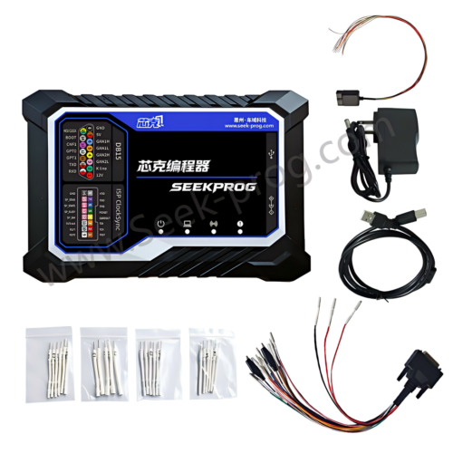
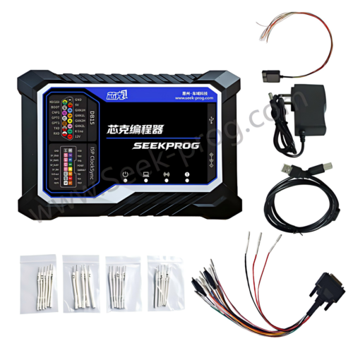
SeekProg for Supported Instrument Cluster Chip Programming
SeekProg is a chip programming solution for supported automotive electronic devices and memory components. Its supported applications include instrument cluster and other automotive module programming, depending on the specific chip, interface and software functions.
For instrument cluster work, technicians should first identify the target component and confirm the required programming method. The chip's manufacturer, complete part number, memory architecture and electrical requirements must be verified before connecting a programmer.
Depending on the supported device, SeekProg provides programming interfaces including JTAG, SPI, I2C, BDM and SWD. Availability varies by target chip, so the current device support information should be checked before starting a repair.
Learn more about the SeekProg Chip Programmer and review its supported programming applications before selecting a procedure for a specific instrument cluster.
Instrument Cluster Repair Checklist
- Vehicle and instrument cluster identified.
- Original symptoms and diagnostic results recorded.
- Cluster label and connector condition photographed.
- Power supply and ground circuits checked.
- Communication problems investigated.
- Target chip and complete part number identified.
- Programming interface and pinout verified.
- Original data backed up when supported.
- File source and compatibility checked.
- Replacement hardware and configuration requirements confirmed.
- Programming result verified.
- Cluster display and communication checked after repair.
- Vehicle identification and mileage records preserved.
- Final repair report completed.
Frequently Asked Questions
Can a faulty instrument cluster be repaired by chip programming?
Sometimes. Chip programming can support certain data-related repairs, but it cannot directly repair every hardware fault. Diagnosis is necessary to determine whether the problem involves memory, software, power supply, communication or physical components.
Do all instrument clusters use EEPROM?
No. Instrument cluster designs vary. Some use standalone EEPROM devices, while others rely on microcontroller-integrated memory or other storage arrangements.
Can I program an instrument cluster without removing the chip?
Some supported devices can be accessed in-circuit, depending on the PCB design and programming method. Other devices may require isolation or removal. Follow the supported procedure for the exact component.
Will copying memory data make every replacement cluster compatible?
No. Compatibility also depends on hardware, software, vehicle configuration and manufacturer-specific adaptation requirements.
Should I back up the original data before repairing a cluster?
When the device and supported procedure allow it, preserve the original data before making changes. Verify the read result and keep an unchanged master copy.
Does successful chip verification mean the instrument cluster is fully repaired?
No. Chip verification checks the relevant programming result. The complete cluster still requires appropriate diagnostic and functional checks.
Why is the original odometer record important?
Odometer information is part of the vehicle's history. Maintaining accurate records helps support lawful repairs, transparent component replacement and compliance with applicable regulations.
Conclusion
Automotive instrument cluster repair can involve electrical diagnosis, communication testing, component replacement and chip-level programming. The correct approach depends on the actual fault, the cluster architecture and the supported programming functions.
Before programming, identify the cluster and target chip, verify the electrical requirements and preserve the original data when possible. When replacing a cluster, confirm hardware and software compatibility and follow the required vehicle configuration procedure.
After repair, verify display functions, diagnostic communication and relevant vehicle information. Careful documentation and appropriate data protection help technicians deliver more reliable instrument cluster repair while preserving the vehicle's service history.
Professional use notice: Instrument cluster programming and electronic repair should be performed by trained technicians for lawful and authorized service. Follow the manufacturer's procedures, protect original vehicle data and comply with applicable regulations concerning odometer information and vehicle records.