Automotive ECU Water Damage Repair: Corrosion Diagnosis and PCB Inspection
Automotive electronic control units operate in demanding environments where vibration, temperature changes, moisture and electrical disturbances can affect long-term reliability. Although many ECUs are housed in protective enclosures, damaged seals, connector leaks, condensation and exposure to water can allow moisture to reach the internal circuit board.
Water damage does not always cause an immediate failure. In some cases, a vehicle continues operating for a period before corrosion, conductive contamination or deteriorating electrical connections produce intermittent faults.
When an ECU develops problems after exposure to moisture, replacing the entire module is not always the first diagnostic step. A systematic inspection can help technicians determine whether the damage is limited to connectors, affects the PCB or has reached critical electronic components.
This guide explains how to inspect a water-damaged ECU, identify common corrosion-related problems, assess whether component-level repair is appropriate and verify the results safely.
1. How Water Damage Affects an Automotive ECU
An ECU contains electronic components connected through conductive tracks, solder joints, connectors and multiple power and communication circuits. Moisture can compromise these connections and, under certain conditions, create unintended electrical paths between conductors.
The severity of the damage depends on several factors, including the type of liquid, exposure duration, electrical state of the module, temperature and PCB construction.
Common consequences include:
- Corrosion on connector terminals and component leads.
- Oxidation of copper traces and exposed metal surfaces.
- Conductive contamination between adjacent PCB connections.
- Damaged solder joints and electrical contacts.
- Short circuits involving power, ground or signal lines.
- Degradation of components exposed to prolonged moisture.
- Intermittent communication and unexplained diagnostic faults.
Water exposure does not automatically mean that every component is defective. The objective of diagnosis is to identify the affected areas and establish whether the original electrical functions can be restored reliably.
2. Recognize Common Symptoms of Water-Damaged ECUs
Water-related ECU problems can produce different symptoms depending on which circuits have been affected.
Possible warning signs include:
- The ECU cannot communicate with diagnostic equipment.
- Intermittent loss of communication with other vehicle modules.
- Unexpected diagnostic trouble codes.
- Engine starting or operating problems associated with ECU faults.
- Unusual current consumption or battery drain.
- Intermittent electrical behavior that changes with temperature or humidity.
- Visible corrosion around the ECU connector or housing.
- Signs of moisture inside the ECU enclosure.
These symptoms are not specific to water damage. Similar problems can arise from defective wiring, weak battery voltage, failed components or unrelated vehicle faults.
Record the original symptoms and diagnostic trouble codes before removing or opening the module. This information provides a useful reference when evaluating the repair results.
3. Make the ECU Safe Before Inspection
Before opening a suspected water-damaged ECU, follow the vehicle manufacturer's procedures for electrical isolation and module removal.
Important precautions include:
- Disconnect the relevant power sources according to the service procedure.
- Follow the required battery disconnection and waiting procedures.
- Inspect the exterior for liquid contamination before handling connectors.
- Avoid applying power to a visibly wet or contaminated module.
- Use appropriate electrostatic discharge precautions when handling electronic components.
- Document the module identification and connector condition.
Do not repeatedly reconnect a module to determine whether it has dried out. Applying power while conductive contamination remains can cause additional damage.
If the liquid may contain fuel, oil, corrosive chemicals or other hazardous substances, use appropriate handling procedures before opening or cleaning the module.
4. Inspect the ECU Housing and Seals
The first inspection should establish how moisture may have entered the enclosure.
Examine the housing, gasket and connector area for:
- Cracked or distorted enclosure sections.
- Damaged seals or gasket surfaces.
- Loose or damaged connector locks.
- Corrosion around external terminals.
- Water marks or residue near the enclosure joints.
- Signs of previous opening or incorrect reassembly.
- Damaged cable entries or mounting points.
Identifying the likely entry point is important because cleaning the PCB without addressing the source of moisture may lead to recurring problems.
Some enclosures are designed for specific sealing procedures and may require replacement seals or manufacturer-approved repair methods. Do not assume that adhesive or a generic sealant is suitable for every ECU housing.
5. Inspect the PCB for Corrosion
After opening the ECU using an appropriate procedure, inspect the circuit board under suitable lighting and magnification.
Look for visible evidence of moisture exposure, including:
- White, green or blue deposits on metal surfaces.
- Darkened or discolored PCB areas.
- Corrosion around component leads.
- Residue beneath connectors or electronic components.
- Damaged solder joints.
- Exposed or deteriorating copper traces.
- Signs of overheating near contaminated areas.
Corrosion color alone cannot identify the exact chemical process or establish the extent of the damage. Some deposits may originate from the PCB finish, solder materials or other contaminants.
Photograph the affected areas before cleaning. These images can help document the original condition and guide subsequent inspection.
Pay particular attention to connectors, fine-pitch integrated circuits, power supply sections and areas where residue may have accumulated under components.
6. Understand Why Corrosion Can Cause Intermittent Faults
Corrosion can affect an electrical connection gradually rather than causing an immediate open circuit.
As conductive surfaces deteriorate, contact resistance may increase. In other situations, contamination can create unintended leakage paths between adjacent connections.
These conditions may cause:
- Unstable supply voltage at an electronic component.
- Intermittent communication signals.
- Unreliable sensor or actuator signals.
- Unexpected resets or controller shutdowns.
- Inconsistent behavior under changing environmental conditions.
A module that works briefly after drying or cleaning is not necessarily fully repaired. Corrosion may remain beneath components, inside connectors or within damaged PCB materials.
Diagnosis should therefore include appropriate electrical measurements and an assessment of the affected circuit, rather than relying exclusively on the ECU's immediate response after cleaning.
7. Check the ECU Power Supply Circuit
The power supply section is a useful diagnostic focus because many internal functions depend on stable electrical power.
Depending on the ECU design, this section may include input protection components, voltage regulators, filtering components and other power management circuitry.
After ensuring that the board is safe to test, inspect the relevant circuit for:
- Corroded supply terminals.
- Damaged input protection components.
- Cracked or contaminated solder joints.
- Short circuits on relevant supply rails.
- Damaged voltage regulators or supporting components.
- Broken PCB traces or vias.
Use the correct circuit documentation and component specifications when taking measurements. Supply voltages and circuit arrangements vary between ECUs.
If a suspected short circuit or unresolved contamination remains, do not apply power simply to see whether the controller starts. Establish the electrical condition first.
8. Inspect Communication and Signal Circuits
Water damage can also affect the circuits responsible for communication between the ECU and other vehicle modules.
Depending on the controller, relevant circuits may include CAN, LIN or other communication interfaces, along with their associated protection and supporting components.
Check for:
- Corrosion around communication connector pins.
- Damaged PCB traces between the connector and interface components.
- Contamination around transceivers and protection devices.
- Short circuits involving signal lines.
- Unstable electrical conditions affecting communication components.
If communication fails, distinguish between a vehicle-side wiring fault and a problem within the ECU. External wiring, power supply and network conditions should be evaluated before replacing internal communication components.
For additional background, see the Automotive CAN Bus Transceiver Diagnosis Guide.
9. Clean Contaminated PCB Areas Carefully
Cleaning may be part of a water-damage repair, but the correct procedure depends on the type of contamination, PCB materials, component construction and manufacturer's requirements.
Before cleaning:
- Document the affected areas.
- Identify sensitive components and materials.
- Determine whether the residue requires a specialized cleaning method.
- Check the compatibility of the proposed cleaning agent.
- Protect components that could be damaged by unsuitable solvents or mechanical action.
Use an appropriate electronics cleaning procedure and suitable tools. Avoid aggressive scraping that could remove component markings, protective coatings or copper traces.
Do not assume that visible residue is the only contamination present. Moisture and corrosive materials may have entered areas that are difficult to inspect without additional equipment.
After cleaning, allow the board to dry fully according to the applicable procedure before performing electrical tests or applying power.
Cleaning can remove contamination, but it cannot restore copper traces, damaged component leads or degraded materials that have already been lost.
10. Determine Whether Component-Level Repair Is Possible
After inspection and appropriate cleaning, assess the extent of the damage before deciding whether the ECU can be repaired.
Potentially repairable problems may include localized connector damage, certain damaged solder joints or isolated component failures where the surrounding PCB remains sound.
More serious conditions may include:
- Severe corrosion extending through multiple PCB layers.
- Extensive loss of copper traces or component pads.
- Damage beneath critical integrated circuits.
- Multiple failed components caused by electrical shorts.
- Corrosion affecting fine-pitch connections that cannot be reliably restored.
- Damage to critical internal circuitry that cannot be verified after repair.
The feasibility of repair depends on the component availability, board construction, diagnostic evidence and required reliability.
A controller should not be considered serviceable merely because visible corrosion has been removed. The repaired circuits must be evaluated against the required electrical and functional criteria.
11. Identify Damaged Chips Before Replacement
When inspection indicates a possible component failure, identify the exact semiconductor device before attempting replacement.
Record the available information:
- Complete component marking.
- Manufacturer and part number, where identifiable.
- Package type and pin arrangement.
- Relevant electrical specifications.
- Function within the affected circuit.
- Compatibility of the proposed replacement.
Do not select a replacement based only on the chip's package size or physical resemblance to another component.
Some ECU chips contain firmware or configuration data, while others perform power management, communication, signal processing or protection functions. A replacement procedure that is appropriate for one type of component may be unsuitable for another.
When a programmable memory device or microcontroller must be accessed, verify whether the required read, write or other operation is supported by the available programming equipment.
See the Automotive MCU and Memory Chip Identification Guide for additional information.
12. Understand When Chip Programming Is Relevant
Not every water-damaged ECU requires chip programming. If the fault is limited to a connector, power supply component or damaged circuit trace, restoring the relevant electrical function may be the primary repair task.
Programming may become relevant when:
- A supported memory device must be read before component replacement.
- Original data needs to be preserved before a controller repair.
- A compatible replacement component requires supported data transfer.
- A controller-specific recovery procedure requires a supported programming operation.
- Data integrity needs to be verified after a supported repair operation.
Before programming, confirm the exact device, the intended operation and the required electrical conditions. Water-damaged components should not be assumed to remain electrically reliable merely because the programmer can recognize them.
Where original data can be read reliably, preserve it unchanged and verify the result. If the memory or its connections are damaged, record that limitation instead of treating an uncertain read as a complete backup.
Learn more from the EEPROM Programming Guide for Automotive ECU Repair.
13. Test the Repaired ECU Before Reinstallation
Before returning the ECU to the vehicle, perform the electrical and functional checks appropriate for the controller and repair.
Depending on the fault, the procedure may include:
- Inspecting the repaired PCB under magnification.
- Checking the affected connections and solder joints.
- Verifying the relevant power and ground circuits.
- Checking for unintended shorts in the repaired area.
- Testing the repaired circuit under the documented conditions.
- Confirming supported communication with the controller.
- Reviewing relevant diagnostic trouble codes.
- Recording the final test results and remaining limitations.
Do not apply power until unresolved shorts, contamination or other electrical hazards have been addressed.
Where a bench test is available, use the correct connection diagram and electrical specifications for the ECU. A successful bench test can provide useful evidence, but it may not reproduce every condition encountered in the vehicle.
14. Verify Vehicle Operation After Reinstallation
After the ECU has been reinstalled, complete the applicable vehicle-level checks.
These may include:
- Confirming that the ECU communicates with diagnostic equipment.
- Checking relevant powertrain or body system diagnostic codes.
- Verifying the functions affected by the original complaint.
- Checking that the enclosure and connectors are properly sealed.
- Confirming that wiring and mounting points are correctly installed.
- Completing any required coding, initialization or adaptation procedures.
If the original problem was intermittent, perform appropriate follow-up testing rather than relying on a single successful start or communication session.
Finally, address the source of the water ingress. If the housing, connector seal or installation location remains vulnerable, the ECU may suffer further damage.
Common Mistakes in ECU Water Damage Repair
Applying Power Before Inspection
Moisture and conductive contamination can create unintended electrical paths. Inspect and assess the module before applying power.
Cleaning Without Finding the Source of the Leak
Cleaning the PCB does not prevent recurring water ingress. Inspect the housing, seals and connectors and address the cause.
Assuming Visible Corrosion Is the Only Damage
Contamination may extend beneath components or into inaccessible areas. Perform the appropriate electrical checks after cleaning.
Replacing Chips Without Confirming the Fault
Water damage can affect multiple parts of a circuit. Identify the failed component through appropriate testing rather than replacing parts based solely on appearance.
Using an Unverified Replacement Component
Similar-looking chips may have different electrical specifications or functions. Confirm the exact part number and compatibility before replacement.
Assuming a Successful Read Means the Memory Is Healthy
A programmer recognizing a device does not establish that every memory region or stored data item is valid. Verify the read result and preserve any limitations in the repair record.
Skipping Final Functional Testing
Removing corrosion does not prove that the ECU has been restored. Complete the required electrical, communication and vehicle-level checks.
ECU Water Damage Inspection Checklist
- Original symptoms and diagnostic codes recorded.
- ECU identification and hardware details documented.
- Module safely isolated before inspection.
- Housing, seals and connector areas inspected.
- PCB corrosion documented before cleaning.
- Power supply and communication circuits assessed.
- Cleaning method checked for material compatibility.
- Board fully dried according to the appropriate procedure.
- Damaged components identified before replacement.
- Programming requirements confirmed where applicable.
- Original data preserved where supported.
- Repaired circuits tested before reinstallation.
- Vehicle-level communication and function checks completed.
- Source of moisture ingress addressed.
Frequently Asked Questions
Can a water-damaged ECU be repaired?
Some ECUs can be repaired when the damage is limited and the affected circuits can be restored and verified. Severe corrosion, multilayer PCB damage or failures involving critical components may make reliable repair impractical.
Can I simply dry an ECU and reconnect it?
Drying alone does not remove corrosion or conductive residue. The module should be inspected, cleaned using an appropriate procedure where necessary and evaluated before power is reapplied.
Does green or white residue always mean the ECU is defective?
No. Residue is evidence that warrants inspection, but its appearance alone does not establish the exact damage or whether the ECU is beyond repair.
Can corrosion cause intermittent ECU communication problems?
Yes. Corroded contacts, damaged traces and conductive contamination can affect electrical signals intermittently. External wiring and power supply faults should also be considered.
Should I replace every chip near a corroded area?
No. Replacement should be based on diagnostic evidence and component condition. Inspect the surrounding circuit and determine which components are actually damaged.
Is chip programming always required after ECU water damage?
No. Some repairs involve only connectors, PCB traces or electronic components. Programming is relevant only when the particular repair requires a supported operation involving programmable memory or a controller.
How can I reduce the risk of recurring ECU water damage?
Identify and correct the source of moisture ingress, inspect the housing and connector seals, install the module according to the applicable procedure and verify that the enclosure is properly secured.
SeekProg for Automotive Electronic Repair
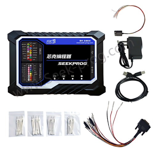
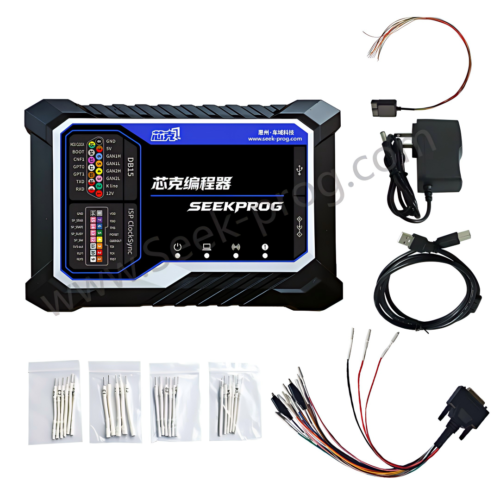
SeekProg provides chip programming equipment for supported semiconductor devices used in automotive electronics and other electronic applications. In a water-damaged ECU repair workflow, programming may be relevant when the identified fault or replacement procedure requires supported access to a programmable memory device or microcontroller.
Programming equipment does not replace the need for electrical diagnosis, PCB inspection or appropriate rework techniques. Before beginning a programming operation, verify the exact chip, supported function and required connection method.
Explore these resources:
- SeekProg Chip Programmer Product Page.
- Automotive MCU and Memory Chip Identification Guide.
- EEPROM Programming Guide for Automotive ECU Repair.
- Automotive CAN Bus Transceiver Diagnosis Guide.
Check the current device support information before selecting a programmer for a specific repair. Compatibility depends on the semiconductor device and the intended operation.
Conclusion
Automotive ECU water damage can affect connectors, PCB traces, power supply circuits, communication interfaces and programmable components. The visible condition of the circuit board is useful evidence, but it does not reveal the full extent of the electrical damage.
A reliable repair process begins with safe inspection, documentation of the original condition and identification of the moisture entry point. Appropriate cleaning, component-level diagnosis and electrical verification can then help determine whether the module can be restored.
Chip programming may support selected recovery or replacement operations, but it should only be used when the identified task and target device are supported. After repair, verify the ECU's electrical behavior, communication and relevant vehicle functions.
Professional safety notice: ECU inspection and PCB repair should be performed by qualified technicians using suitable ESD protection, compatible cleaning materials, verified circuit information and appropriate test equipment. Do not energize a contaminated or potentially shorted module, and complete the required safety and functional checks before returning the vehicle to service.