
KT200II ECU Programmer vs Chip Programmer: Which Workflow Does Your Workshop Need?
Protocol-based ECU programming and direct chip programming solve different workshop problems. Understanding where KT200II fits into the repair process helps technicians select a safer and more efficient route for identification, reading, writing, backup, cloning and recovery.
Automotive electronics workshops often use both ECU programmers and chip programmers, but the two categories should not be treated as interchangeable. An ECU programmer communicates with a supported control unit through a defined vehicle or controller protocol. A chip programmer works directly with an individual memory device or microcontroller through a compatible interface.
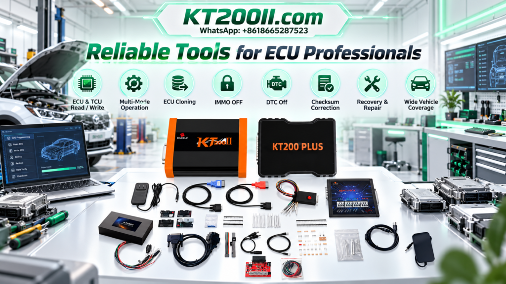
The KT200II ECU Programmer is designed around professional ECU and TCU workflows. It provides supported communication through OBD, Bench, Boot, JTAG and BDM modes, depending on the exact vehicle and controller protocol.
A direct chip programmer becomes relevant when a repair requires access to a removed memory device, a supported circuit-board connection or another component-level procedure. The correct tool depends on the controller condition, required data and available technical documentation.
What Is a Protocol-Based ECU Programmer?
A protocol-based ECU programmer communicates with the ECU or TCU as a complete control unit. Instead of treating the memory chip as an isolated component, the programmer follows a defined communication process for the controller family.
Depending on the supported KT200II protocol, the available operations may include:
- ECU or TCU identification
- Virtual Read
- Physical Flash reading
- EEPROM or processor-memory reading
- Calibration writing
- Full or partial backup
- ECU and TCU cloning
- Checksum processing where supported
- Selected recovery procedures
The exact functions are not universal. Technicians should search the vehicle, ECU, TCU, processor or connection method in the KT200II Supported ECU List before beginning a job.
What Is a Direct Chip Programmer?
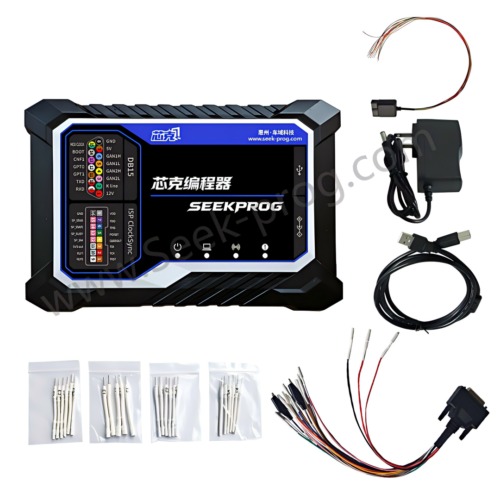
A direct chip programmer communicates with a memory device or microcontroller rather than relying on the complete ECU communication protocol. Depending on the device and equipment, the connection may use an adapter, test clip, socket, probe, direct wiring or removal of the chip from the circuit board.
Common component-level targets can include:
- Serial EEPROM devices
- Parallel Flash memory
- Microcontrollers
- Dashboard and body-module memory
- Airbag-module memory
- Immobilizer-related memory in lawful repair work
- Industrial and automotive electronic components
Direct chip access can be useful when the ECU no longer communicates through its normal interface. However, it requires accurate chip identification, compatible voltage, correct pin orientation, suitable adapters and advanced soldering or circuit-board experience.
KT200II ECU Programming
Works through controller-specific protocols and connection diagrams. It is generally the first tool category to consider when the ECU remains supported and accessible.
- Vehicle-side OBD operation
- Direct Bench connection
- Boot-level access
- JTAG and BDM support
- Protocol-defined backup and writing
Direct Chip Programming
Works with an individual chip or processor using a compatible electrical interface. It is commonly associated with deeper component-level repair.
- Socket or adapter connection
- In-circuit or removed-chip work
- Manual device identification
- Raw memory reading and writing
- Board-level repair experience
KT200II vs Chip Programmer Comparison
| Comparison | KT200II ECU Programmer | Direct Chip Programmer |
|---|---|---|
| Primary target | Complete supported ECU or TCU | Individual memory chip or microcontroller |
| Communication basis | Vehicle and controller protocol | Chip interface and device specification |
| Typical connection | OBD, Bench, Boot, JTAG or BDM | Socket, clip, adapter, direct wiring or desoldered chip |
| Controller identification | Often available through the selected protocol | The technician normally identifies and selects the device |
| File structure | Protocol may define Flash, EEPROM, microcontroller data or Virtual Read | Often provides raw memory based on the selected device and read range |
| Physical intervention | May range from no ECU removal to opening the housing | May require opening, probing, soldering or removing the chip |
| Best starting point | Supported ECU and TCU programming, backup, cloning and recovery | Component-level work when direct memory access is required |
| Main risk | Wrong protocol, unstable power, incorrect wiring or unsuitable file | Wrong voltage, reversed orientation, poor soldering or incorrect device selection |
When KT200II Should Be the First Choice
For most supported ECU and TCU jobs, the protocol-based route should be evaluated before component removal. It can preserve the original circuit board and provide controller-specific instructions for identification, connection and memory operations.
Supported OBD Reading or Writing
When the exact controller offers OBD access, KT200II may communicate through the vehicle diagnostic connector while the ECU remains installed. This can reduce disassembly and preserve the original ECU sealing.
OBD support does not mean every ECU can be physically read. Some protocols may provide Virtual Read, writing or identification only. Always confirm the function shown for the exact entry.
Bench Programming and ECU Cloning
Bench mode connects directly to the external ECU or TCU connector. It is frequently used when a controller has been removed for testing, backup, replacement or cloning.
Technicians must follow the complete diagram, including all required positive supplies, grounds, ignition terminals, wake-up lines and communication connections. Review the official KT200II operation-mode information before choosing between OBD, Bench, Boot, JTAG and BDM.
Boot, JTAG or BDM Access
Selected controllers require deeper processor-level access. KT200II can provide Boot, JTAG or BDM procedures where these interfaces are included in the supported protocol.
These modes may offer additional memory areas or a recovery path, but they should not be selected merely because they appear more advanced. Use only the interface specified for the exact controller and processor.
When Direct Chip Programming May Be Required
A chip programmer may become necessary when no suitable ECU communication protocol exists or when damage prevents the controller from entering its normal programming mode. It may also be used for a component-level repair that specifically requires raw memory access.
- The ECU does not power up normally
- Communication circuits are damaged
- A memory device must be tested outside the controller
- The repair procedure requires a raw chip dump
- The supported ECU protocol cannot access the required memory area
- A corrupted device must be replaced and programmed
- The controller is part of a specialized electronic module rather than a supported ECU protocol
Can KT200II and a Chip Programmer Work Together?
Yes. In a professional repair workflow, the two tool categories can complement each other. KT200II may provide ECU identification, protocol-based files and a controlled connection method, while direct chip equipment may support component testing or specialized memory work.
For example, a technician may first use KT200II to identify a working controller and save every available original memory area. If later diagnosis confirms a damaged memory device, a chip programmer may be used as part of the component-level repair. After the electronic repair, KT200II can be used again to test communication and complete the supported controller workflow.
The important principle is to preserve traceability. Every file must be labeled with its source, tool, protocol, memory type and date.
Professional Combined Workflow
- Record the vehicle and controller information.
Photograph the complete ECU or TCU label and note the vehicle model, year, engine, transmission and service history. - Check KT200II compatibility.
Search the exact controller in the current official support database and review the listed operations. - Select the least invasive supported mode.
Use OBD, Bench, Boot, JTAG or BDM according to the protocol and required data. - Save ECU identification.
Record hardware, software and calibration references before changing controller data. - Create all available original backups.
Save Flash, EEPROM, microcontroller memory or full backup data where the protocol provides them. - Diagnose the communication or hardware fault.
Do not move to chip-level work until wiring, power and protocol selection have been verified. - Identify the exact memory device.
If component-level work is necessary, confirm the chip marking, package, voltage and compatible programming method. - Read and verify the chip more than once.
When practical, compare repeated reads to detect unstable connections or incorrect settings. - Keep raw and processed files separate.
Never overwrite the first original read or confuse a complete dump with a calibration-only file. - Reassemble and test through the supported ECU protocol.
After repair, verify identification and communication before final installation or vehicle testing.
File Management for ECU and Chip Programming
Files obtained through an ECU protocol and files read directly from a chip may differ in size, byte order, address range and content. A raw chip dump should not automatically be written through an ECU programming protocol, and a protocol-formatted file should not automatically be treated as a complete chip image.
| File Record | Information to Save |
|---|---|
| ECU identification | Hardware number, software number, calibration reference and protocol screenshot |
| KT200II read | Selected vehicle, ECU protocol, connection mode, memory type and file size |
| Chip read | Complete chip marking, selected device, adapter, voltage, read range and verification result |
| Modified file | Source original, modification type, checksum status and person responsible |
| Write operation | Written file, tool, protocol, date, voltage behavior and completion result |
Power and Connection Safety
Both tool categories depend on correct electrical preparation. A protocol-based ECU connection may require several power and ground terminals, while a chip programmer must use the voltage and pin configuration required by the exact semiconductor device.
- Correct ECU or chip identified
- KT200II protocol verified
- Connector orientation checked
- Every required ground connected
- Permanent positives confirmed
- Ignition and wake-up lines confirmed
- Communication wiring verified
- Regulated voltage prepared
- Current behavior monitored
- Unused leads insulated
- Chip pin-one orientation confirmed
- Adapter compatibility checked
- Laptop power secured
- USB connection protected
- Original data saved first
- Recovery plan prepared
Common Mistakes to Avoid
Using Chip Programming as the First Response to No Communication
No communication can result from the wrong KT200II protocol, missing ignition supply, poor ground, incorrect connector orientation or damaged CAN wiring. Eliminate setup problems before opening the ECU or removing a component.
Assuming Similar Chips Are Interchangeable
Devices with similar markings may use different voltage, capacity, pinout or programming algorithms. Select the exact supported device rather than the nearest-looking name.
Confusing EEPROM and Flash Data
EEPROM may contain configuration, coding or adaptation-related information, while Flash commonly contains operating software and calibration data. The exact layout varies by controller, so one memory area cannot automatically replace another.
Writing the First File Found Online
A file must match the controller hardware, software, memory area and protocol requirements. File size alone cannot confirm compatibility.
Failing to Verify Repeated Reads
If two reads from the same chip differ, the connection may be unstable. Do not write or modify the data until the cause has been identified.
Frequently Asked Questions
Is KT200II a chip programmer?
KT200II is primarily a professional ECU and TCU programmer. It communicates through supported controller protocols using OBD, Bench, Boot, JTAG and BDM modes. Its workflow differs from a universal programmer that targets individual chips directly.
Can KT200II read EEPROM and Flash?
Selected KT200II protocols may provide EEPROM, Flash, microcontroller memory or full-backup operations. Available memory areas depend on the exact controller and protocol.
Should I use KT200II before removing an ECU chip?
When the controller is supported and still communicates, verify the KT200II protocol and save all available data before considering chip removal. This preserves identification information and may provide the required file without component-level intervention.
Is Bench mode the same as direct chip programming?
No. Bench mode normally communicates with the complete ECU through its external connector. Direct chip programming communicates with a specific memory device or processor through its own electrical interface.
Where can I check whether KT200II supports my ECU?
Search the vehicle, ECU, TCU, controller family, processor or connection mode in the official KT200II compatibility database.
Where should I download KT200II software?
Use the current package and installation resources provided through the official KT200II Software Download page.
Official KT200II Resources
Use the official KT200II pages to understand the product, compare programming modes, confirm ECU and TCU compatibility, obtain software resources and review professional technical guides.
Final Thoughts
KT200II and a direct chip programmer belong to different levels of automotive electronics work. KT200II provides controller-specific communication for supported ECU and TCU identification, reading, writing, backup, cloning and recovery. A chip programmer provides direct access to compatible memory devices and microcontrollers when component-level work is genuinely required.
The safest process begins with exact controller identification and a search of the current KT200II support database. Use the supported protocol, save all available original data and diagnose power or communication faults before moving to a more invasive repair method.
When both tool categories are used, maintain complete file records and never assume that raw chip data and protocol-formatted ECU files are interchangeable. Careful preparation and traceable backups are more important than choosing the deepest available access method.
Professional and authorized use notice: ECU, TCU and semiconductor reading, writing, cloning, coding and recovery should only be performed by trained technicians on vehicles and electronic modules they are legally authorized to service. Available functions and memory data depend on the exact controller, processor, hardware revision, software version, selected KT200II protocol and chip-programming method.