
Automotive ECU Output Driver Diagnosis: MOSFET, Relay and Solenoid Circuit Repair
Automotive electronic control units do more than process sensor signals and store software. They must also control electrical loads, including relays, solenoids, motors, valves and, depending on the system design, fuel injectors and other actuators.
These functions rely on output driver circuits that convert low-power control signals into electrical outputs capable of operating external devices. Depending on the ECU architecture, these circuits may use MOSFETs, bipolar transistors, integrated driver ICs, relay control stages and protective components.
When an output driver develops a fault, the vehicle may experience an inoperative actuator, an electrical circuit diagnostic code or an intermittent operating problem. Replacing the entire ECU without identifying the failed circuit can lead to unnecessary costs.
This guide explains how automotive ECU output drivers work, how to recognize common failure symptoms, how to inspect MOSFET and relay driver circuits, and how to verify a component-level repair.
1. What Is an Automotive ECU Output Driver?
An ECU output driver is an electronic circuit that controls an electrical load in response to commands from the controller's processing system.
The microcontroller may generate a low-power logic signal, but the external device can require a different voltage, current capacity or switching arrangement. The output driver provides the interface between the control logic and the load.
Depending on the ECU design, output drivers may control:
- Automotive relays.
- Solenoids and electrically operated valves.
- Fuel injectors in applicable engine management systems.
- Electric motors and other actuators.
- Heating elements and selected electrical loads.
- Warning lamps or other switched outputs.
Not every ECU uses the same driver architecture. Some circuits use discrete transistors, while others use integrated power driver ICs with built-in current monitoring, thermal protection or short circuit detection.
Before testing a suspected driver, identify the controlled load and obtain the appropriate circuit information for the exact ECU.
2. Understand the Main Types of Output Driver Circuits
MOSFET drivers
MOSFETs are semiconductor devices commonly used for electronic switching. Depending on the circuit design, they can control substantial load currents while being driven by a suitable control signal.
Automotive ECUs may use N-channel or P-channel MOSFETs in different circuit configurations. The device's voltage rating, current capability, gate requirements and thermal characteristics must match the application.
A MOSFET can fail in several ways, including a drain-to-source short circuit, an open circuit or degraded switching performance. External circuit faults can also make a functioning MOSFET appear defective.
Bipolar transistor drivers
Some ECU output stages use bipolar junction transistors to switch or amplify control signals. Their operating requirements differ from those of MOSFETs.
When testing a bipolar transistor, consider its base, collector and emitter connections, the surrounding resistors and the intended switching configuration.
Relay driver circuits
Relay driver circuits control an electromagnetic relay that switches another electrical circuit. The driver may operate the relay coil directly or through an integrated control stage.
Depending on the design, the circuit may also include a flyback diode or another suppression arrangement to limit voltage transients generated when the coil is switched off.
Integrated smart drivers
Modern automotive electronics may use integrated driver ICs that combine switching elements, diagnostic feedback and protective functions.
These devices may report overcurrent, overtemperature or open-load conditions. A diagnostic warning does not necessarily mean that the IC itself has failed; the external load, wiring and operating conditions must also be investigated.
3. Recognize Common Output Driver Failure Symptoms
Output driver faults can produce symptoms that resemble wiring failures, defective actuators or software problems.
Common symptoms include:
- An actuator does not operate when commanded.
- A relay fails to energize or remains energized unexpectedly.
- A solenoid circuit reports an electrical fault.
- A relevant output remains continuously active.
- An ECU repeatedly reports a short circuit or open circuit.
- A fuse opens when a particular circuit is activated.
- The fault appears only under certain temperatures or operating conditions.
- A component or PCB area shows signs of overheating.
These symptoms are clues rather than proof of a defective semiconductor.
For example, a relay that does not activate may have a broken coil, a missing power supply, damaged wiring, an incorrect control command or a failed driver transistor.
Record the diagnostic trouble codes and the conditions under which the problem occurs before opening the ECU.
4. Step One: Identify the Controlled Load and Circuit
Before performing board-level testing, identify the output that is not functioning correctly.
Record the following information where available:
- Vehicle manufacturer, model and production year.
- ECU manufacturer and complete part number.
- Hardware revision and software identification.
- The affected actuator or relay.
- Relevant diagnostic trouble codes.
- Whether the fault is permanent or intermittent.
- Any recent wiring, actuator or ECU repairs.
Use the correct wiring diagram to identify the ECU connector terminal, external load, supply circuit and expected control arrangement.
Do not assume that a particular connector pin controls the same function across different ECU versions. Similar controllers can use different pin assignments and driver configurations.
5. Step Two: Rule Out External Wiring and Load Faults
Before testing the ECU's internal output stage, investigate the external circuit. A defective actuator or shorted harness can damage a healthy driver or trigger its protective functions.
Check the relevant circuit for:
- Damaged insulation and exposed conductors.
- Corroded or loose connector terminals.
- Short circuits to power or ground.
- Open circuits between the ECU and the load.
- Incorrect replacement components.
- Damaged actuator coils or excessive load current.
- Missing or unstable power supplies.
Use the manufacturer's specified testing procedure and disconnect components where required before taking resistance measurements.
Do not apply external power directly to an ECU output pin unless the documented test procedure explicitly requires it. An incorrect connection can damage the driver or other internal circuits.
If an external load is shorted, replacing the ECU driver without correcting the original fault may result in another failure.
6. Step Three: Inspect the ECU PCB
If the external circuit has been evaluated and internal damage is suspected, inspect the ECU circuit board using appropriate lighting and magnification.
Look for:
- Burned or discolored components.
- Cracked solder joints.
- Damaged PCB traces.
- Corrosion around the output stage.
- Cracked packages or damaged component leads.
- Heat damage near high-current components.
- Damaged resistors or protective components around the driver.
Photograph the affected area before performing any rework. Record the component markings and identify the relevant circuit connections using the PCB layout or available technical documentation.
Visible damage can help narrow the investigation, but a component that looks normal may still have an internal electrical fault.
7. Step Four: Identify the MOSFET Correctly
When a MOSFET is suspected, identify the complete part number before selecting a replacement or attempting detailed electrical testing.
Relevant information includes:
- Manufacturer and component marking.
- Package type and pin arrangement.
- Drain, source and gate connections.
- Maximum drain-to-source voltage rating.
- Current and power dissipation ratings.
- Gate drive requirements.
- On-resistance and thermal characteristics.
The package shape alone is not sufficient for component identification. Two devices with similar housings may have different pinouts, voltage ratings or switching characteristics.
Also determine whether the MOSFET is a low-side switch, high-side switch or part of a more complex circuit. The correct testing method depends on the topology.
For further information about semiconductor identification, read the Automotive MCU and Memory Chip Identification Guide.
8. Step Five: Check the MOSFET for Electrical Faults
With the ECU safely disconnected and the applicable procedure followed, preliminary measurements can help identify certain MOSFET failures.
Depending on the circuit and device, checks may include:
- Inspecting for a drain-to-source short circuit.
- Checking for unexpected conduction between relevant terminals.
- Examining the gate circuit and associated resistors.
- Checking for damaged PCB traces around the device.
- Comparing measurements with the component datasheet and known-good reference information.
In-circuit measurements must be interpreted carefully. Other components connected to the MOSFET can create alternate current paths, so a reading taken on the assembled PCB may not represent the device's behavior in isolation.
A multimeter can identify some obvious faults, but it cannot establish that every MOSFET performs correctly under its intended switching conditions.
If the measurements are inconclusive, use a suitable diagnostic procedure to isolate the device or assess the circuit further. Do not remove a component unnecessarily before checking the surrounding circuit.
9. Step Six: Diagnose a Relay Driver Circuit
A relay driver circuit typically switches current through a relay coil. The driver may be a discrete transistor, a MOSFET or an integrated device.
If a relay does not operate, investigate both the external relay and the ECU's control circuit.
Where the circuit documentation permits, check:
- Relay coil resistance against the specified value.
- Availability of the required relay supply voltage.
- Ground and control signal conditions.
- The driver transistor or MOSFET.
- Associated gate or base resistors.
- Flyback or transient suppression components.
- Relevant PCB connections and solder joints.
Some relays are controlled on the ground side, while others use high-side switching or another arrangement. Confirm the circuit topology before interpreting voltage readings.
A relay click does not necessarily prove that the switched contacts are functioning correctly. Likewise, a relay that remains inactive does not prove that the ECU driver has failed.
10. Step Seven: Investigate Injector and Solenoid Driver Faults
Injector and solenoid control circuits may operate under demanding electrical conditions. Their requirements vary significantly with the engine management system, actuator type and ECU architecture.
Depending on the application, the output stage may include switching transistors, current control circuitry, protective components and diagnostic feedback.
When a related fault occurs, examine:
- Actuator coil condition and specified resistance.
- Harness continuity and insulation.
- Connector condition and terminal fit.
- Driver output stage and associated components.
- Power supply and grounding requirements.
- Available ECU diagnostic data.
- The control strategy and test conditions specified by the manufacturer.
Some injector circuits use specialized high-voltage or peak-and-hold driver arrangements. Generic low-voltage tests may be unsuitable for these circuits.
Do not apply an arbitrary test voltage to injector or solenoid outputs. Use approved test equipment and the correct service information for the target ECU.
Where the fault may involve a high-energy driver stage, follow the applicable electrical safety procedures before performing measurements.
11. Step Eight: Inspect Protective and Supporting Components
The output transistor is not always the only component responsible for a failed output.
Depending on the circuit design, supporting components may include:
- Gate or base resistors.
- Current-sensing resistors.
- Flyback diodes.
- Transient voltage suppression devices.
- Driver ICs and gate driver circuits.
- Filtering and protection components.
A failed protection component can create a short circuit or alter the behavior of the output stage. A damaged gate driver can also prevent a functioning MOSFET from switching correctly.
When a transistor appears defective, investigate the surrounding circuit to determine whether another component caused the failure.
This approach helps reduce repeat failures and avoids replacing a driver without correcting the underlying electrical problem.
12. Step Nine: Replace the Defective Component When Justified
If testing confirms a failed output component and repair is appropriate, select a replacement that meets the requirements of the original circuit.
Before replacement, confirm:
- The exact component identity.
- Electrical ratings and pinout.
- Switching characteristics and gate drive requirements.
- Package compatibility and thermal performance.
- Availability of an appropriate replacement.
- The condition of the PCB pads and nearby traces.
A component with a higher current rating is not automatically a suitable replacement. Differences in switching speed, gate charge, on-resistance, thermal behavior or protection characteristics can affect circuit operation.
Use suitable electronic rework equipment and ESD precautions. Avoid overheating the PCB, lifting pads or creating solder bridges between adjacent terminals.
After installing the replacement, inspect the solder joints and check for unintended shorts before applying power.
13. Step Ten: Verify the Repair Under Appropriate Conditions
A component replacement should be followed by electrical and functional verification.
Depending on the circuit, the checks may include:
- Visual inspection of the repaired area.
- Checking relevant power and ground connections.
- Verifying that no unintended shorts remain.
- Confirming the condition of the external load and wiring.
- Testing the output using the documented procedure.
- Checking diagnostic feedback where available.
- Confirming that the original fault no longer occurs under the required conditions.
Use appropriate current-limited test equipment and approved load-testing methods where required. Do not operate an output stage with an unknown or potentially shorted load.
After reinstallation, check the relevant diagnostic trouble codes and vehicle functions. If the original fault was intermittent, additional testing may be needed to establish that the repair is reliable.
Common ECU Output Driver Repair Mistakes
Replacing the MOSFET Before Checking the Load
A shorted actuator or damaged harness may be responsible for the original failure. Correct the external fault before returning the ECU to service.
Assuming Every Output Uses the Same Circuit
Low-side drivers, high-side drivers, relay circuits and specialized injector stages have different requirements. Identify the actual topology before testing.
Using a Similar-Looking Replacement Component
Package appearance does not guarantee compatible voltage ratings, pin assignments or switching characteristics. Verify the exact device specifications.
Testing an Integrated Circuit Without Understanding Its Protection Features
Smart driver ICs may disable an output under certain electrical or thermal conditions. Investigate the reported fault and operating conditions before concluding that the IC is defective.
Ignoring Supporting Components
Gate drivers, current-sensing resistors and protective devices can affect output behavior. Inspect the surrounding circuit when diagnosing a failed transistor.
Skipping Post-Repair Verification
A replaced component does not establish that the original problem has been resolved. Verify the circuit, external load and relevant vehicle functions.
ECU Output Driver Diagnosis Checklist
- Vehicle and ECU identification recorded.
- Affected actuator or relay identified.
- Diagnostic trouble codes and original symptoms documented.
- External wiring and load checked.
- ECU safely disconnected before board inspection.
- PCB condition and component markings documented.
- Driver topology and component specifications verified.
- MOSFET, transistor or driver IC tested using an appropriate method.
- Supporting protection components inspected.
- Replacement component compatibility confirmed.
- Rework quality inspected.
- Electrical checks completed before applying power.
- Output operation verified using the documented procedure.
- Final diagnostic and functional checks recorded.
Frequently Asked Questions
What causes an automotive ECU output driver to fail?
Possible causes include shorted external loads, damaged wiring, electrical transients, excessive current, overheating, corrosion and component aging. The actual cause should be established before replacing the driver.
Can a multimeter identify a defective MOSFET?
A multimeter can detect some obvious faults, such as certain drain-to-source short circuits. However, in-circuit measurements can be affected by surrounding components, and more advanced testing may be necessary to evaluate switching performance.
Can a failed relay driver prevent a relay from operating?
Yes. A defective driver can prevent the relay coil from receiving the required control current. However, the relay, external wiring, power supply and control command should also be checked.
Can a shorted injector damage the ECU?
A shorted or otherwise defective load can overload an output circuit. Some ECUs incorporate protective features, but protection varies by design and does not guarantee that the driver will survive every fault.
Should I replace an entire driver IC or repair individual components?
The appropriate approach depends on the circuit design, confirmed fault, component availability and repair requirements. Diagnose the failure first and use a repair method that can be verified reliably.
Does an ECU output driver fault require chip programming?
Not usually. Many output driver faults require electrical diagnosis and component-level repair rather than memory programming. Programming may be relevant to a separate operation when a supported programmable device or controller function is involved.
How can I prevent a replacement driver from failing again?
Investigate the original cause, including external load condition, wiring faults, supply problems and damaged protection components. Replacing the failed semiconductor without correcting the underlying problem can lead to another failure.
SeekProg for Supported Automotive Chip Programming
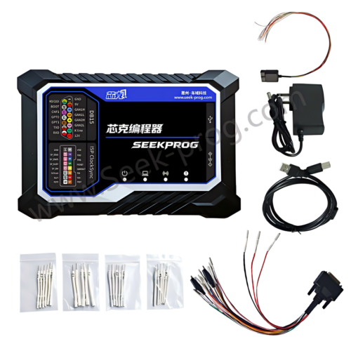
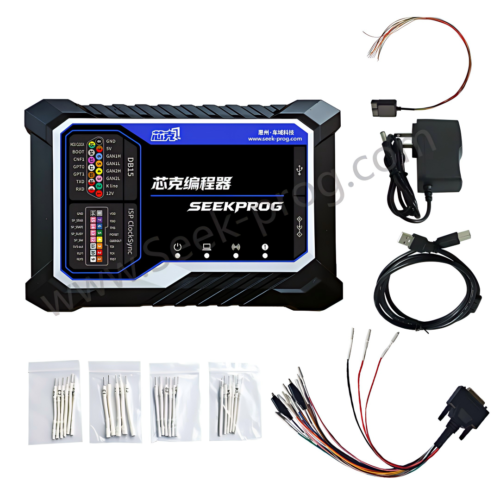
SeekProg provides chip programming equipment for supported semiconductor devices used in automotive electronics and other electronic applications.
When repairing an ECU output stage, the primary task is to identify and verify the defective electrical component. MOSFETs, transistors and driver ICs do not all require the same programming procedure, and many output driver repairs do not involve chip programming at all.
Programming equipment may be relevant when the wider repair also requires a supported operation on a memory device or microcontroller. Always verify the exact device, interface and intended function before beginning.
Explore these SeekProg resources:
- SeekProg Chip Programmer Product Page.
- Automotive MCU and Memory Chip Identification Guide.
- JTAG, SPI, I2C, BDM and SWD Programming Guide.
- EEPROM Programming Guide for Automotive ECU Repair.
Check the current supported-device information before selecting a programming tool for a specific automotive electronics job.
Conclusion
Automotive ECU output driver circuits control many of the electrical loads required for engine management and other vehicle functions. When a driver fails, the symptoms may resemble wiring problems, defective actuators or other ECU faults.
A reliable diagnosis begins by identifying the controlled load and verifying the external circuit. Technicians can then inspect the PCB, identify the driver architecture, test the relevant components and investigate the surrounding protection circuitry.
When component replacement is justified, electrical compatibility and repair quality must be verified. The external cause of the original failure should also be corrected to reduce the risk of repeat damage.
By combining circuit-level diagnosis with appropriate component identification and post-repair testing, automotive electronics technicians can make more informed decisions about ECU output stage repair.
Professional safety notice: Perform ECU circuit testing and PCB rework using suitable equipment, verified circuit documentation and appropriate electrical safety precautions. Never apply power to an unknown or potentially shorted output circuit, and complete the required functional checks before returning the vehicle to service.