
Automotive CAN Bus Diagnostics: How to Identify Communication Faults Before ECU Repair
Modern vehicles rely on communication networks to exchange information between electronic control units. The engine ECU, transmission controller, body control module, instrument cluster and other systems may depend on these networks to coordinate vehicle functions.
The Controller Area Network (CAN) is one of the communication technologies widely used in automotive electronics. When a CAN network develops a fault, technicians may encounter communication errors, multiple warning lights, missing diagnostic data or several electronic modules becoming unavailable at the same time.
However, a communication failure does not automatically indicate a defective ECU. Damaged wiring, poor electrical connections, incorrect termination, power supply problems or another module disrupting the network can produce similar symptoms.
This guide explains how to diagnose automotive CAN bus problems, distinguish network faults from ECU hardware failures and determine when further electronic inspection or supported chip-level repair may be appropriate.
What Is an Automotive CAN Bus?
CAN is a communication protocol that allows compatible electronic control units to exchange messages over a shared network. Instead of requiring a separate communication wire for every piece of information, multiple controllers can transmit and receive messages over a common communication bus.
Depending on the vehicle architecture, CAN communication may support functions involving:
- Engine management and powertrain coordination.
- Transmission control and operating information.
- Body electronics and comfort functions.
- Instrument cluster information and warning indicators.
- Chassis and vehicle dynamics systems.
- Diagnostic communication between supported control units.
Modern vehicles may contain multiple CAN networks operating at different speeds or serving different functions. Gateways and other network components may connect these networks or control communication between them.
Consequently, a fault affecting one network does not necessarily mean that every electronic system in the vehicle is defective.
Common Symptoms of CAN Bus Communication Problems
CAN-related faults can produce symptoms across several vehicle systems. The exact behavior depends on which network is affected, which messages are missing and how the vehicle responds to communication failures.
Common symptoms include:
- Diagnostic equipment cannot communicate with one or more control units.
- Several electronic modules report communication-related trouble codes.
- Warning lights appear unexpectedly on the instrument cluster.
- Engine or transmission information is unavailable to related modules.
- Some electronic functions operate intermittently.
- A control unit disappears from the diagnostic network.
- Communication problems occur after wiring repairs or module replacement.
- Network faults appear after water ingress, collision damage or electrical repairs.
These symptoms are useful diagnostic clues, but they do not identify the failed component by themselves.
For example, if several modules report missing messages from the same ECU, the cause could be the ECU's power supply, its network connection, a wiring fault or an internal communication circuit problem.
Technicians should establish which modules are affected and whether the faults share a common network path before replacing any controller.
Understanding CAN-H and CAN-L
A conventional high-speed CAN network commonly uses two communication conductors: CAN-High (CAN-H) and CAN-Low (CAN-L). The transceiver inside a compatible electronic module converts electrical signaling on these conductors into digital information that the controller can process.
The network's electrical characteristics depend on the CAN implementation and vehicle design. High-speed CAN, low-speed CAN and other automotive network arrangements should not be assumed to share identical electrical specifications.
When inspecting a CAN circuit, technicians should identify:
- The correct network and its intended communication function.
- The CAN-H and CAN-L terminals for the specific connector.
- The location of relevant network branches and junctions.
- The specified termination arrangement.
- The modules connected to the affected network.
- Any gateway or intermediate communication components.
Use the vehicle-specific wiring diagram rather than relying on generic connector pinouts. Similar-looking control units may have different terminal assignments.
Step 1: Scan the Vehicle Before Disconnecting Modules
A complete diagnostic scan can provide valuable information about the network before any wiring or module connections are changed.
When communication is available, record:
- Which electronic control units respond to the diagnostic tool.
- Which modules cannot be accessed.
- Current and stored communication-related trouble codes.
- Fault descriptions identifying missing or invalid messages.
- Relevant freeze-frame or event information, where available.
- Whether the reported faults appeared together or at different times.
Pay particular attention to communication faults reported by multiple modules. Several controllers reporting the same missing message may point toward a shared network problem rather than several independent ECU failures.
Save the original diagnostic report before clearing codes. Clearing the faults too early may remove useful evidence about the initial failure.
Step 2: Identify Which Network Is Affected
A vehicle may contain several communication networks, and a diagnostic connector can provide access to more than one system through the vehicle's network architecture.
Before testing the wiring, determine which network connects the affected modules.
Useful information includes:
- The vehicle's network topology diagram.
- The location of the affected controllers.
- Relevant gateway connections.
- Network splice and junction locations.
- Communication paths between the diagnostic connector and target ECU.
For example, if the engine ECU communicates normally but a group of body control modules does not, investigate the network shared by those modules rather than immediately focusing on the engine ECU.
The network layout must be confirmed using the correct vehicle documentation. Do not assume that all modules are connected to one continuous CAN bus.
Step 3: Check ECU Power Supply and Ground Connections
A controller cannot reliably communicate if its power supply or ground connection is missing or unstable. This can make a healthy ECU appear defective or unavailable on the network.
Before suspecting an internal CAN transceiver fault, inspect the relevant electrical circuits.
- Check the specified fuses and power supply paths.
- Verify the ECU's required ground connections.
- Inspect connectors for corrosion, moisture or damaged terminals.
- Check for loose connections or previous wiring repairs.
- Measure supply conditions using the documented procedure.
- Investigate unexpected voltage drops under appropriate operating conditions.
A basic continuity check may not reveal every electrical problem. A connection can appear continuous while developing excessive resistance under load.
Use suitable electrical measurement methods and the manufacturer's specifications to determine whether the controller is receiving the required power.
Step 4: Inspect CAN Wiring and Connectors
Physical wiring faults are common causes of communication problems, particularly in vehicles that have experienced collision damage, water ingress, previous electrical work or harsh operating conditions.
Inspect the affected network for:
- Broken or stretched conductors.
- Corroded or contaminated connector terminals.
- Loose terminal contacts.
- Damaged insulation or exposed conductors.
- Incorrectly repaired twisted-pair wiring.
- Aftermarket devices connected incorrectly to the network.
- Water ingress near connectors or electronic modules.
CAN wiring may use twisted-pair conductors to help reduce electromagnetic interference. Follow the manufacturer's requirements when repairing or replacing damaged wiring.
Do not assume that visually intact insulation proves that the conductors or terminals are electrically sound. Inspect the circuit using the appropriate diagnostic method.
Step 5: Measure CAN Network Electrical Characteristics
Electrical measurements can help distinguish certain wiring and termination faults from other communication problems. However, the correct test depends on the network type, vehicle design and current operating state.
Resistance Testing
Some CAN networks use termination resistors at defined locations. On a conventional high-speed CAN network with a documented two-termination arrangement, the combined resistance measured across CAN-H and CAN-L with the network correctly powered down and isolated as specified may be approximately 60 ohms.
This is a common reference value, not a universal specification for every automotive network. Other topologies, additional circuits, connected modules or measurement conditions can produce different readings.
Before performing a resistance test:
- Confirm the vehicle's specified test procedure.
- Switch off the required power sources.
- Allow the system to enter the prescribed state.
- Identify the correct measurement points.
- Consider connected modules and network branches.
Never use a resistance measurement on a powered circuit unless the equipment and procedure explicitly permit it.
Voltage Testing
CAN voltage measurements depend on the network implementation and communication state. A digital multimeter may help identify certain wiring faults, but it may not reveal the timing or waveform details needed to diagnose intermittent communication errors.
Compare measurements with the manufacturer's specifications and use an appropriate oscilloscope or network analyzer when a more detailed signal examination is required.
Oscilloscope Testing
An oscilloscope can display the communication waveform and help identify abnormalities such as excessive noise, distorted edges or unexpected signal behavior.
Interpret the waveform according to the applicable network standard and vehicle architecture. Use suitable probes and measurement techniques to avoid shorting the communication lines or damaging connected electronics.
Step 6: Understand Common CAN Bus Fault Patterns
Different electrical faults can produce different communication symptoms. The following table provides general diagnostic directions rather than definitive fault identification.
| Observed condition | Possible causes | Recommended investigation |
|---|---|---|
| One ECU is unavailable | Missing power, poor ground, local wiring fault or internal ECU problem | Check ECU power, ground, connector and local network connection |
| Several ECUs on one network are unavailable | Shared wiring fault, network short, termination problem or gateway issue | Review network topology and test the affected network section |
| Intermittent communication | Loose terminals, damaged wiring, electrical interference or unstable supply | Inspect connections and evaluate signals under the relevant conditions |
| Multiple missing-message codes | A shared message source is unavailable or communication is disrupted | Identify the source ECU and determine whether it communicates correctly |
| Communication changes after module replacement | Incorrect part, wiring error, configuration mismatch or an installation issue | Verify replacement compatibility and inspect the affected connections |
| Abnormal network waveform | Electrical loading, wiring damage, termination problems or a faulty transceiver | Compare the waveform with the correct network specification |
Use these patterns to guide testing, not to replace a structured diagnosis. The same symptom can have several causes, and the actual fault must be confirmed with appropriate evidence.
Step 7: Determine Whether an ECU Is Disrupting the Network
A defective electronic module can sometimes affect other devices sharing the same network. For example, an internal electrical fault may load the communication lines or prevent normal signaling.
However, disconnecting modules without a plan can create additional diagnostic trouble codes or change the network's electrical characteristics.
Before isolating a controller:
- Review the network topology and manufacturer instructions.
- Identify the modules connected to the affected network.
- Determine the appropriate isolation procedure.
- Record the initial diagnostic information.
- Follow the required power-down and reconnection sequence.
Where the documented procedure permits module isolation, observe whether the network behavior changes after the specified component is disconnected.
A change in network behavior can provide useful evidence, but it does not automatically prove that the disconnected module is defective. The result must be interpreted alongside the wiring layout, termination arrangement and other diagnostic findings.
Do not disconnect safety-critical modules or perform unapproved tests that could affect vehicle safety.
Step 8: Inspect the ECU's Internal Communication Circuit
If external wiring, power supply, ground connections and network conditions have been verified, an internal ECU fault may need further investigation.
Depending on the controller design, the communication circuit may contain a CAN transceiver, protective components and supporting circuitry that connect the external network to the controller's processor.
Possible causes of internal communication failure include:
- Damage to the CAN transceiver.
- Electrical overstress.
- Corrosion or moisture damage on the circuit board.
- Damaged solder joints or PCB tracks.
- Power supply circuit faults affecting communication components.
- Other internal hardware failures.
Internal inspection should follow external circuit diagnosis. Replacing a transceiver or attempting chip-level programming will not solve a network wiring fault elsewhere in the vehicle.
When board-level repair is necessary, identify the exact component and verify its specifications, pinout and replacement compatibility before performing any work.
Step 9: Understand the Difference Between Communication Repair and Chip Programming
CAN bus diagnostics and chip programming address different aspects of automotive electronic repair.
CAN diagnostics investigates the communication network, electrical connections and controller accessibility. Chip programming involves supported operations on programmable semiconductor devices or control unit memory.
Chip programming may be relevant when a diagnosed ECU fault involves supported firmware, memory data or another programmable component. It is not a general solution for every CAN communication failure.
Before choosing a programming operation, establish:
- Whether the ECU hardware is functioning correctly.
- Whether the communication fault has been isolated to the controller.
- Whether the intended memory or processor operation is supported.
- Whether the original data can be preserved.
- Whether the proposed repair method matches the identified fault.
If the ECU cannot communicate through the normal vehicle network, another supported access method may be available for certain controllers. However, direct access depends on the specific ECU, programming tool and documented procedure.
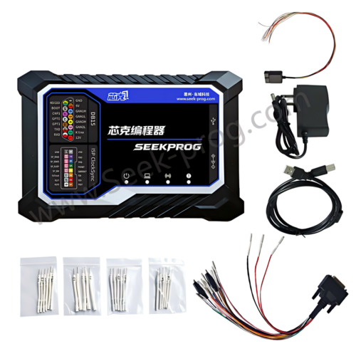
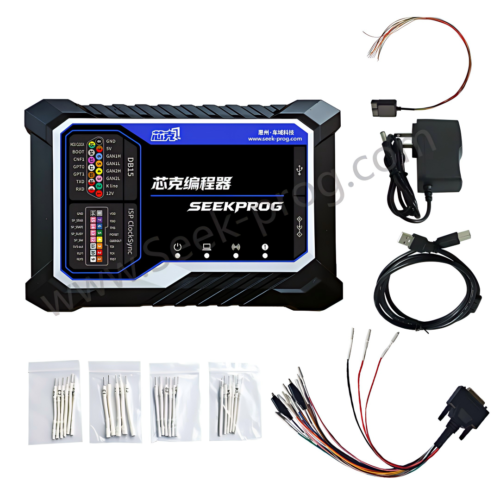
Learn more about supported chip-level operations in the SeekProg Chip Programmer product information.
Step 10: Verify the Network After Repair
After repairing wiring, replacing a component or completing a supported ECU repair, verify the network's operation before returning the vehicle to service.
The final checks may include:
- Inspecting the repaired wiring and connector installation.
- Confirming that the affected ECUs receive the required power and ground.
- Checking communication with the relevant control units.
- Reviewing current diagnostic trouble codes.
- Confirming that the original communication complaint has been resolved.
- Checking relevant network signals when necessary.
- Completing required configuration or initialization procedures.
- Saving the final diagnostic report.
Some stored communication codes may remain after a fault has been repaired and may require a documented clearing and verification procedure. Confirm whether any codes return after the system is operated under the appropriate conditions.
Do not rely solely on the fact that an ECU now responds to the diagnostic tool. Verify the relevant functions and ensure that the original network fault is no longer present.
Common CAN Bus Diagnostic Mistakes
Replacing an ECU Before Checking Its Power Supply
A controller without a reliable power supply or ground connection may appear completely unresponsive. Verify the electrical circuits before condemning the ECU.
Assuming Every Communication Code Indicates a Network Short
Communication codes can result from a missing module, a failed message source, gateway problems or other conditions. Review the complete diagnostic context before selecting a test.
Applying One Resistance Specification to Every CAN Network
Network topologies and termination arrangements vary. Confirm the expected measurement and test conditions for the exact vehicle.
Measuring Resistance on a Powered Network
Resistance testing normally requires the circuit to be in the prescribed unpowered state. Follow the manufacturer instructions and use the correct test points.
Replacing a CAN Transceiver Without Confirming the Fault
An internal transceiver fault is only one possible cause of communication failure. Confirm the external network, power supply and ground conditions first.
Using Chip Programming to Solve a Wiring Problem
Programming cannot repair an open circuit, poor terminal contact or defective network connection. Identify the actual fault before selecting an electronic repair method.
SeekProg for Supported Automotive Chip Programming
SeekProg is a chip programming solution for supported semiconductor devices and automotive electronic applications. Depending on the target device and available software functions, it may be used for selected programming operations involving supported electronic modules.
CAN bus diagnosis should generally be completed before selecting a chip-level repair. If the evidence indicates an internal controller fault involving supported programmable hardware or memory, technicians can then evaluate the appropriate repair procedure.
Available programming operations depend on the exact semiconductor device, module architecture and supported software functions. Support for a particular communication protocol does not guarantee support for every ECU or CAN-related repair.
For more information, visit the SeekProg Chip Programmer page and confirm the supported device and operation before beginning a specific repair.
CAN Bus Diagnostic Checklist
- Original symptoms and diagnostic trouble codes recorded.
- Affected control units identified.
- Vehicle network topology reviewed.
- Relevant ECU power and ground circuits checked.
- CAN wiring and connectors inspected.
- Applicable electrical test conditions confirmed.
- Resistance or voltage measurements interpreted using vehicle-specific specifications.
- Network waveform inspected when required.
- Potentially disruptive modules isolated only through an approved procedure.
- Internal ECU communication circuitry considered only after external checks.
- Chip-level repair selected only when supported by the diagnostic evidence.
- Communication and vehicle functions verified after repair.
- Final diagnostic results saved.
Frequently Asked Questions
What causes automotive CAN bus communication failures?
Potential causes include damaged wiring, poor connector contacts, missing ECU power or ground, incorrect termination, a faulty network component or an internal ECU communication circuit failure. The actual cause must be confirmed through diagnosis.
Can a bad ECU cause multiple CAN communication errors?
Yes. An unavailable ECU or a controller disrupting the network can cause communication errors in other modules. However, several missing-message codes can also result from wiring, power supply or gateway faults.
Is a 60-ohm resistance reading always correct for CAN bus testing?
No. Approximately 60 ohms is a common reference for certain high-speed CAN networks with two specified 120-ohm terminations, measured under the correct unpowered conditions. Other network designs and measurement conditions can produce different results.
Can a multimeter identify every CAN bus fault?
No. A multimeter can help check selected electrical conditions, but intermittent faults and waveform abnormalities may require an oscilloscope or other suitable diagnostic equipment.
Should I replace the ECU if it cannot communicate?
Not immediately. Check the controller's power supply, ground, connectors and network wiring first. If the external circuits are correct, investigate the controller and the supported diagnostic access methods.
Can chip programming repair a CAN bus fault?
Only when the underlying problem involves a supported programmable component or data-related fault. Programming cannot correct damaged wiring, incorrect termination or other external electrical problems.
What should I check after repairing a CAN network?
Verify communication with the affected modules, review current diagnostic codes, confirm that the original fault no longer occurs and complete the required functional checks. Save the final diagnostic results for the repair record.
Conclusion
Automotive CAN bus diagnostics is an important step in modern electronic vehicle repair. Communication problems can originate from wiring, power supplies, connectors, network components or internal ECU circuitry, so replacing a controller without testing the surrounding system can lead to unnecessary repairs.
A systematic process begins with diagnostic scans and network identification, followed by electrical checks, wiring inspection and appropriate signal measurements. Only after external causes have been investigated should technicians consider internal ECU communication circuit repair or supported chip-level operations.
By identifying the actual cause and verifying network operation after repair, technicians can improve diagnostic accuracy, reduce unnecessary component replacement and maintain reliable automotive electronic systems.
Professional use notice: Automotive network diagnosis and ECU repair should be performed by qualified technicians using vehicle-specific wiring diagrams, appropriate measuring equipment and supported procedures. Follow the manufacturer's electrical and safety requirements, especially when working with powered vehicle networks or safety-critical control units.